
Data Sheet for Product


14
Siemens CE1N4510en
Smart Infrastructure 2020-11-26
Connection diagrams
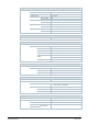
SAV31P00
A Actuator
L Phase
N Neutral
N1 Controller
Y1, Y2 Positioning signals
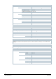
SAV61P00
A Actuator
F2 Frost protection thermostat: terminals:
1 – 2 frost hazard / sensor is interrupted (thermostat closes with frost)
1 – 3 normal operation
F3 Thermal reset limit thermostat
F4 Frost protection monitor with 0…1000 Ω signal output, does NOT support QAF21.. or QAQ61..
M Measuring neutral
N1 Controller
SN System zero
SP System potential AC/DC 24 V
U Position feedback - (System neutral is measuring ground M)
Y Positioning signal
Z Control signal forced control