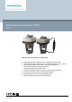
ACVATIX™ Electromotoric actuators for VPI46.. SAY..P.. Actuators with 15 mm stroke and 200 N force ● ● ● ● ● ● ● A6V10628469_en--_e 2020-11-26 SAY31P03 Operating voltage AC 230 V, positioning signal 3-position SAY61P03 Operating voltage AC/DC 24 V, positioning signal 0...10V, 4...
Use Electromotoric actuators to operate Siemens combi valves for type series VPI46.40F9.5Q and VPI46.50F12Q with 15 mm stroke, as control valves on ventilation, air conditioning, district heating and refrigeration plants. Functions Function Description Type 3-position control A 3-position signal controls the actuator via connection terminals Y1 or Y2. The desired position is transmitted to the valve. Modulating control The modulating positioning signal provides stepless motor control.
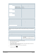
Type summary Type Item No. Stroke Positionin Operatin g force g voltage SAY31P03 1) S55150-A132 SAY61P03 2) S55150-A133 AC 230 V Positioning signal Spring Positionin LED return g time time 3-position Manual adjuster Auxiliary functions 3) - DC ...10 V SAY61P03/MO 2) S55150-A145 SAY81P03 2) S55150-A134 15 mm 200 N AC 24 V DC 24 V DC 4...20 mA - 0...
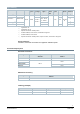
Spare parts Product number / Stock number Housing cover Screw (valve stem coupling) U-bracket 8000060843 Equipment combinations Valve type DN VPI46.40F9.5Q S55264-V129 40 VPI46.50F12Q S55264-V130 50 H100 Min. m100 Δpmin [mm] [l/h] [l/h] [kPa] 15 1370 9500 25 1400 11500 36 Data sheet N4855 Product documentation Title Contents Document ID Actuators SAX.., SAY.., SAV.., SAL..
Notes Safety CAUTION National safety regulations Failure to comply with national safety regulations may result in personal injury and property damage. ● Observe national provisions and comply with the appropriate safety regulations. WARNING Risk of burns from hot actuator brackets The actuator brackets on heating plants can also become hot from the contact with the hot valve during operation. The temperature of the actuator bracket can reach 100 °C.
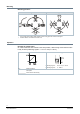
Mounting Mounting positions Indoor application Outdoor application 1) 2) 1) Only together with weather shield ASK39.2. IP54 housing protection remains unchanged. 2) SAY61P../MO is not intended for outdoor use. Operation Direction of control action On valves where the stem retracts to the close position, "direct acting" means that the value is fully closed at positioning signal Y = 0 V or Z = 0 Ω (i.e. 100 %). Direct acting Y, Z Positioning signal R Flow speed Positioning signal Y DC 0...10 V, 4.
Maintenance The actuators are maintenance-free. Disposal The device is considered an electronic device for disposal in accordance with the European Guidelines and may not be disposed of as domestic garbage. ● Dispose of the device through channels provided for this purpose. ● Comply with all local and currently applicable laws and regulations. Warranty service Technical data on specific applications are valid only together with Siemens products listed under "Equipment combinations".
Technical data Power Operating voltage SAY31P03 AC 230 V ±15% SAY61P03.. AC 24 V ± 20 % / DC 24 V +20 % / -15 % (SELV / PELV) SAY81P03 Frequency 45...65 Hz External supply line fusing (EU) ● Non-renewable fuse 6...10 A slow ● Circuit break max. 13 A, tripping characteristic B, C, D to EN 60898 ● Power source with current limitation of max. 10 A Power consumption at 50 Hz SAY31P03 SAY61P03 SAY61P/MO 6 VA / 3.5 W Stem retracts/extends SAY81P03 Typical inrush current 1) 8 VA / 3.75 W 8.
Communication SAY61P../MO Communication protocol Modbus RTU RS-485, not galvanically isolated Number of nodes Max. 32 Address range 1...248 / 255 Factory setting Transmission formats 255 1-8-E-1 / 1-8-O-1 / 1-8-N-1 / 1-8-N-2 Factory setting 1-8-E-1 Factory setting Auto Baud rates (kbaud) Auto / 9.6 / 19.2 / 38.4 / 57.6 / 76.8 / 115.
Environmental conditions Operation IEC 60721-3-3 Climatic conditions Class 3K5 Mounting location Indoors (weather-protected) Temperature, general -5...55 °C Humidity (non-condensing) 5...95 % r.h. Transportation 4) IEC 60721-3-2 Climatic conditions Class 2K3 Temperature -25...70 °C Humidity < 95% r.h. Storage IEC 60721-3-1 Climatic conditions Class 1K3 Temperature -15...55 °C Humidity 5...95 % r.h. Max.
Connection diagrams Internal Diagrams SAY31P03 Accessories 1 x ASC10.51 SAY61P.. Accessories SAY61P03 1 x ASC10.
SAY81P03 Accessories 1 x ASC10.51 Connection terminals SAY31P03 AC 230 V 3-position System neutral (SN) Positioning signal (actuator’s stem extends) Positioning signal (actuator’s stem retracts) SAY61P03 AC / DC 24 V D 0...10 V 4...20 mA 0...1000 System neutral (SN) System potential (SP) Positioning signal for DC 0...10 V / 4...
SAY81P03 AC / DC 24 V 3-position System potential (SP) Positioning signal (actuator’s stem extends) Positioning signal (actuator’s stem retracts) Connection diagrams SAY31P03 A Actuator L Phase N Neutral N1 Controller Y1, Y2 Positioning signals SAY61P03 A Actuator F2 Frost protection thermostat: terminals: 1 – 2 frost hazard / sensor is interrupted (thermostat closes with frost) 1 – 3 normal operation Siemens Smart Infrastructure F3 Thermal reset limit thermostat F4 Frost protection m
SAY61P03/MO A Actuator N1 Controller G System potential AC/DC 24 V G0 System zero REF Reference line (Modbus RTU) + Bus + (Modbus RTU) - Bus - (Modbus RTU) SAY81P03 14 Siemens Smart Infrastructure A Actuator N1 Controller SN System zero SP System potential Y1, Y2 Positioning signals A6V10628469_en--_e 2020-11-26
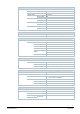
Dimensions Actuator Type A B C C1 C2 D E [mm] SAY..P.. SAY61P03/MO With ASK39.1 1) Siemens Smart Infrastructure 1) [kg] 242 124 150 68 82 80 267 154 300 200 100 - 100 100 200 1.780 1.930 2.
External Modbus converter Dimensions in mm Type X SAY61P03/MO 1) [mm] [kg] 250 0.15 1) Included in total weight. Revision numbers Type Valid from rev. no. SAY31P03 ..A SAY61P03 ..B SAY61P03/MO ..B SAY81P03 ..B Issued by Siemens Switzerland Ltd Smart Infrastructure Global Headquarters Theilerstrasse 1a CH-6300 Zug Tel. +41 58 724 2424 www.siemens.