
Operating instructions

Installation and maintenance
4.2 Connecting
Industrial Ethernet SCALANCE X-100 and SCALANCE X-200 Product Line
Operating instructions, 09/2006, A5E00349864 Release 7
4-7
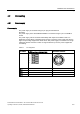
The following errors/faults can be signaled by the signaling contact:
• The failure of a link at a monitored port.
• The failure of one of the two redundant power supplies.
• Incompatible C-PLUG was inserted (only with SCALANCE X-200).
The connection or disconnection of a communication node on an unmonitored port does not
lead to an error message.
The signaling contact remains activated until the error/fault is eliminated or until the current
status is applied as the new desired status using the button.
Exception:
On the SCALANCE X208PRO, the signaling contact remains activated until the error/fault is
eliminated or until the current status is applied as the new desired status by Web Based
Management.
When the device is turned off, the signaling contact is always activated (open).
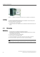
4.2.3 Grounding
Installation on a DIN rail
The device is grounded over the DIN rail.
S7 standard rail
The device is grounded over its rear panel and the neck of the screw.
Wall mounting
The device is grounded by the securing screw in the unpainted hole.
Please note that the SCALANCE X-100 and SCALANCE X-200 must be grounded over one
securing screw with minimum resistance.
If a device of the SCALANCE X-100 and SCALANCE X-200 product line is mounted on a
non-conducting base, a grounding cable must be installed. The grounding cable is not
supplied with the device. Connect the paint-free surface of the device to the nearest
grounding point using the grounding cable.
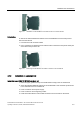
4.2.4 Fitting the IE FC RJ-45 Plug 180
Assembly of the IE FC RJ-45 Plug 180 on an IE FC Standard Cable
For information on assembling an IE FC RJ-45 Plug 180 on a SIMATIC NET Industrial
Ethernet FastConnect cable, please refer to the instructions supplied with the IE FC RJ-45
Plug.