
Operating instructions

Configuration / diagnostics using remote mechanisms
5.2 Configuration with Web Based Management (WBM)
Industrial Ethernet SCALANCE X-100 and SCALANCE X-200 Product Line
Operating instructions, 09/2006, A5E00349864 Release 7
5-55
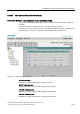
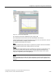
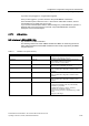
Figure 5-40 POF fiber-optic diagnostics
The vertical axis shows the available link power margin in dB.
The horizontal axis shows the time since the SCALANCE X-200 started up.
If the SCALANCE X-200 is synchronized with a time server, this is the time base. If there is
no time synchronization, the display starts at 00:00:00.
The diagram itself is divided into two areas:
White:
There is an adequate link power margin for problem-free operation. When the SCALANCE
X-200 is installed, the link power margin should be in this range.
Yellow:
If the link power margin enters this range, maintenance is necessary. The boundary of the
yellow area is at a link power margin of 2 dB. To ensure long-term functionality of the
system, the maintenance should be performed. If the link power margin is in the yellow
range, this is signaled by the FO LED lighting up.
Notice
The page for diagnostics of fiber-optic cable only shows correct link power margins when
plastic optical fiber (POF) is used. If polymer cladded fiber (PCF) is used, diagnostics is not
possible.