High Resolution 31 cm/12" LCD-Monitor SCD 1297 Operating Instructions SCD 1297-C/CT (1) (Chassis) 6GF6240-3MA (-3MB with Touch) SCD 1297-E/ET/ETH/ETC/ETB (1) (Mountable) 6GF6240-4MA (-4MB with Touch) 6GF6244-4MB/ 6GF6240-4MC/6GF6242-4MB SCD 1297-R/RT (1)(Rack 19") 6AV8100-0CA00.0AA1/6AV8100-0CB00-0AA1) 6GF6240-6MA01 (-6MB01 with Touch) Copyright Siemens AG LCD-Monitor SCD1297 Page 1 / 19 DOC-No.: B3 0071D1.
No part of this document may be reproduced or transmitted without express permission. Violations will result in prosecution. All rights reserved. 2001 All rights reserved 이 기기는 업무용(A급) 전자파 적합기기로서 판매자 또는 사용자는 이 점을 주의하시기 바라며 가정 외의 지역에서 사용하는 것을 목적으로 합니다. LCD-Monitor SCD1297 Page 2 / 19 DOC-No.: B3 0071D1.
Contents 1 Overview ..................................................................................................................................... 4 1.1 Layout of this Handbook ...................................................................................................... 5 1.2 Warnings and Safety Notes ................................................................................................. 6 1.2.1 Instructions for Handling Assemblies Susceptible to Electrostatic Shock ..............
1 Overview The LCD monitor SCD 1297 has been developed and constructed especially for industrial applications. This monitor can be used in applications where a standard CRT-device would be unsuitable, due to space or environmental restrictions. Its compact enclosure opens up a wide spectrum of possible application areas for the SCD 1297, ranging from air-conditioned computer rooms behind a switching cabinet door, to the immediate vicinity of machinery in a special protective enclosure.
1.1 Layout of this Handbook This handbook should be kept within reach while installing and operating the LCD-monitor. It has been laid out so that even inexperienced users can find the information they require. Chapters are clearly arranged according to subject. In detail, the chapters are arranged as follows: • Chapter 1 Introduction This chapter provides a brief description of the SCD 1297, including its properties, application areas and special features.
1.2 Warnings and Safety Notes Transport The LCD-monitor should only be transported in its original packaging to ensure it will be protected against shocks and rough handling. Setting up When installing the monitor, it should be noted whether any moisture (condensation) has entered the unit during transport or storage. Additional important installation information can be found in the “Technical Data” chapter. EMC This is a Class A piece of equipment (industrial use).
1.2.1 Instructions for Handling Electrostatic Shock Assemblies Susceptible to Most of the assemblies within the SCD 1297 LCD-monitor contain components which can be destroyed by electrostatic voltages. It is also possible for the assemblies to be damaged in such a way that total failure does not occur.
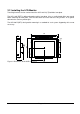
2.2 Installing the LCD-Monitor Two fixing brackets can be used to mount the SCD 1297-C(CT) behind a front plate. The SCD 1297-E(ET) is delivered together with a front plate. It has a sealing band all the way round. When mounting the front plate, care must be taken to ensure that the O-ring remains in its groove otherwise the seal may not be tight. The SCD1297-R(RT) is designed for mounting in a standard 19“ rack system. Supporting rails are not necessary. 329 307 40 5x20 ACTIVE AREA 246x184.
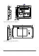
40 M3x10 A 76 4 Figure 2: Dimensions of the SCD 1297-E/ET 483 465 40 SIEMENS A ACTIVE AREA 246x184.5 + - 265.9 190.4 ON 76 4 Figure 3: Dimensions of the SCD 1297-R/RT LCD-Monitor SCD1297 Page 9 / 19 DOC-No.: B3 0071D1.
Thermal Problems In order that the LCD-monitor maintains an optimum operating temperature while in use, air must be allowed to circulate freely around the SCD 1297 enclosure. It is particularly important that the rear of the system is kept free. Please bear in mind that increased temperatures can lead to defects and to a significant reduction in the lifetime of the monitor. EMC Problems This LCD-monitor is a piece of equipment designed for building into an industrial system.
A high-quality 75-ohm coaxial cable must be used for the VGA-signals. Low quality cables can result in interference and shadowing on the display. VGA-Interface The VGA interface is a standard 15-pin male HD-D-type connector. Figure 4: VGA Interface Pin 1 2 3 4 5 6 7 8 9 10 11 12 13 14 15 Signal Video input RED Video input GREEN Video input BLUE Not used Not used GND (RED) GND (GREEN) GND (BLUE) Not used GND Not used Not used H-Sync. V-Sync. Not used LCD-Monitor SCD1297 Page 11 / 19 DOC-No.: B3 0071D1.
Power Supply Power is supplied to the SCD 1297 via a standard power connector on the rear of the unit. Pin O Name GND +12V Description Power supply ground GND Power supply +12VDC 2.4 Electrical Installation Before connecting the SCD 1297 to the power supply, a check should be carried out as to whether the VGA connector is plugged in properly and that the screws are tightened. There is a compartment on the rear of the unit to hold the standard power supply unit delivered with the display.
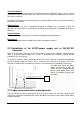
3 Operation and Alignment This chapter contains a description of all the operating and alignment functions. 3.1 Location of the Operation and Alignment Controls All the controls are accessible from the rear of the unit. Their exact position in shown in Figure 1 on page 32. These controls are used for navigating in the OSD menu and for selecting and altering parameters.
3.2 Using and Adjusting the Converter Since there are no standards for video output signals from VGA cards, the first time the unit is switched on it will automatically adjust itself to the graphic card currently being used. 3.2.1 OSD-Menu The „On Screen Display“ OSD is a menu system, which is shown on the display. With the help of OSD and the described controls elements, all adjustments of the monitor are executable. There are just 4 keys S1 to S4 to control the OSD.
3.2.2. Quick-OSD-Menu-Functions Following adjustments can do via the Quick-OSD-menu: Brightnes Contrast Auto adjust Invoke via key Function Contrast Brightness Adjustment/value Range: 0 to 100 via key <+>/<-> Range: 0 to 100 via key <+>/<-> Description Contrast adjustment Brightness adjustment Invoke via key <+> Function Adjustment/value Description Automatic image adjustment Press key <+> to start the adjustment Perform an automatic image adjustment.
3.2.3.
Main menu Function Adjust function / value / range Description Option 2 DPMS ON – OFF Display Power Management System (DPMS) on or off If DMPS activated, the monitor is turn off (backlight) when a synch signal is left. The screen is dark. Source scan OFF – ON – Standard Standard: ON Note: To scan new video source is not relevant because the monitor has one RGB input source only. Blank color red – reen – blue – black Choose the background color of the screen when no input signal is present.
4 Technical Data 4.1 Display Module Type Diagonal Display area (WxH) Resolution Pitch Colours Backlight Brightness (typical) Colour active TFT-LCD 30.8 cm (12.1") 246 x 184.5 mm² 800 x 600 pixels 0.33 x 0.33 mm² 262144 2xCCFT (Cold Cathode Fluorescent Tube) approx. 250 cd/m² 4.2 Power Supply Input voltage Power consumption (normal operation) Power consumption (StandBy) 11.4 – 12.6 VDC approx. 18 W approx. 5 W 4.
4.5 Enclosure Weight Enclosure material Enclosure colour approx. 3.2 kg steel light basic 4.6 Input Signals Level (Video) Bandwidth Impedance Synchronisation 0.7Vss RGB analogue at 75Ω 140Mhz (-3dB) 75Ω Sep. Sync. (TTL) Sync on green Composite Sync 30 to 97 kHz 50 to 100 Hz** H-Frequency V-Frequency 4.