Operating Instructions Control Panel SCD 1297-K (1) Operating Instructions SCD 1297-K (1) (Rack 19") 6AV8100-0BC00-0AA1 (Int.ID:6GF66240-7MA01) SCD1297-KT (1) 6GF6240-7MB Copyright Siemens AG Control Panel SCD 1297-K Page 1 / 31 DOC-Nr.: B4 0003E1.
Operating Instructions No part of this document may be reproduced or transmitted without express permission. Violations will result in prosecution. All Rights reserved. 2001 All Rights reserved. Control Panel SCD 1297-K Page 2 / 31 DOC-Nr.: B4 0003E1.
Operating Instructions Contents 1. Overview................................................................................................................... 5 1.1. Layout of this Handbook ............................................................................................ 6 1.2. Warnings and Safety Notes ....................................................................................... 7 1.2.1. Instructions for Handling Assemblies Susceptible to Electrostatic Shock............ 8 2.
Operating Instructions Figures Fig. 2: Connecting the SCD 1297-K to the computer system over a short distance....................... 16 Fig. 3: Connecting the SCD 1297-K to the computer system over a longer distance ..................... 17 Fig. 4: Key definition table ............................................................................................................. 19 Fig. 8: Keyboard matrix ........................................................................................................
Operating Instructions 1. Overview The SCD 1297-K is a control panel for PC-compatible computer systems and can be used as a man machine interface (MMI) platform for a wide variety of visualisation systems. Special interfaces make it possible to have the SCD 1297-K in a different location as the computer system. Ninety-four keys and a “finger mouse” are provided for software control and operation. The 94 keys can be individually configured.
Operating Instructions 1.1. Layout of this Handbook This handbook should be kept within reach when installing and operating the SCD 1297-K. It has been laid out so that even inexperienced users can find the information they require. Chapters are clearly arranged according to subject. In detail, the chapters are arranged as follows: • Chapter 1 Introduction This chapter provides a brief description of the SCD 1297-K, including its properties, application areas and special features.
Operating Instructions 1.2. Warnings and Safety Notes Transport The LCD monitor should only be transported in its original packaging. This is the only way to ensure it will be protected against shocks and rough treatment. Setting up When installing, it should be noted whether any moisture (condensation) has entered the unit during transport or storage. Additional important installation information can be found in the “Technical Data” chapter.
Operating Instructions 1.2.1. Instructions for Handling Assemblies Susceptible to Electrostatic Shock Most of the assemblies within the SCD 1297-K contain components which can be destroyed by electrostatic voltages. It is also possible for the assemblies to be damaged in such a way that total failure does not occur.
Operating Instructions 2. General Installation Preparation for installing the LCD monitor includes the following points: • Removal of all packaging • Checking of components for damage • Comparison of components received with those on the delivery note • Connection to the computer system and power supply • Building into your system, bearing in mind technical and ergonomic aspects 2.1.
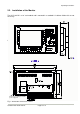
Operating Instructions 2.2. Installation of the Monitor The SCD 1297-K is a 19” rack module and is mounted in a standard 19” cabinet. Guide rails are not necessary. SI EM EN S 25 Bracket for mounting the AC/DCpower supply unit Fig. 1: Dimensions of the SCD 1297-K Control Panel SCD 1297-K Page 10 / 31 DOC-Nr.: B4 0003E1.
Operating Instructions Control Panel SCD 1297-K Page 11 / 31 DOC-Nr.: B4 0003E1.
Operating Instructions Thermal Problems In order that the SCD 1297-K maintains an optimum operating temperature while in use, air must be allowed to circulate freely around the enclosure. This is especially important for the rear of the unit. A convection current must be allowed to circulate around the enclosure Please bear in mind that increased temperatures can lead to defects and to a significant reduction in the lifetime of the monitor.
Operating Instructions 2.3. Interfaces Buttons for OSD X8 X9 X2 X27 X4 X3 X1 X6 X7 2.3.1. VGA-Interface X1 The VGA interface is a standard 15-pin female HD-D-type connector. Pin 1 2 3 4 5 6 7 8 9 10 11 12 13 14 15 Signal Video input RED Video input GREEN Video input BLUE Not used Not used GND (RED) GND (GREEN) GND (BLUE) Not used GND Not used Not used H-Sync. V-Sync. Not used Control Panel SCD 1297-K Page 13 / 31 DOC-Nr.: B4 0003E1.
Operating Instructions 2.3.2. External Keyboard X2 A standard PS2 keyboard can be connected at the rear of the unit. This keyboard will then work in parallel with the built in keyboard on the front of the unit. Pin 1 2 3 4 5 6 Signal Data GND +5V CLK - 2.3.3. PC Interface Keyboard X3 This interface provides the keyboard connection to the computer system and is a standard PS2 female connector.
Operating Instructions 2.3.5. PC Interface Keyboard/Mouse (Long Distance) X27 This interface is used when the computer system and the control panel are separated by more than 5m. The mouse and keyboard signals are transmitted via a common cable. A standard CAT5/6/7 ethernet cable with an RJ45 connector is used.
Operating Instructions 2.3.7. Power Supply X7 / X8 / X9 Power is supplied to the SCD 1297-K via a DC connector, X7, on the rear of the unit. The DC input (12V) has been design to make it impossible to connect the supply voltage the wrong way round. As described in Chapter 2.2.1 on page 12, the SCD 1297-K can be supplied using an AC/DC power supply unit or a DC/DC converter. X7 X8 X9 DC input (12V) AC input (100-240V) DC input (24V) 2.4.
Operating Instructions If the control panel and the computer system are further apart or if there are strong interference fields in the vicinity then the second variation using the special interface (long distance, X27) should be used for the mouse and keyboard. Here, both mouse and keyboard signals are transmitted over one cable, a standard CAT 5/6/7 ethernet cable (note the signal configuration).
Operating Instructions 3. Operation and Alignment This chapter contains a description of the operating and alignment functions. 3.1. Location of the Operation and Alignment Controls The operating controls such as the keyboard and mouse are accessible from the front of the unit. Buttons for aligning the display are located on the rear of the unit. The location of the 4 keys for the OSD can be seen in Fig. 1: Dimensions of the SCD 1297-K on page 10.
Operating Instructions 3.2.2. Key Definition Table Various keywords, characters and syntax are used in the table. The table, which is supplied with the control panel, contains definitions for all of the keys with permanent labels. ; Key table for control panel XXY at plant ZYX ; #Name Simatictable 23 ; ;Basic level, level 0 ; X (0...11) Y (0...7) 0 1 2 3 4 5 6 7 MF-II Key No. 0 19 0 38 0 17 0 18 0 11 0 6 0 83 0 76 Flags T T T T T T T T ; ; ; ; ; ; ; ; Comments E K Q W 0 5 Cursor Up Delete Fig.
Operating Instructions Syntax of a table entry X key co-ordinate Y key co-ordinate Key number Flag Comment The individual entries like X key co-ordinate and Y key co-ordinate must be separated by a space. Key co-ordinates This matrix co-ordinate specifies the key to be defined. Fig. 5 on page 30 in the appendix shows all the SCD 1297-K keys and their co-ordinates. Key number The key number refers to the equivalent MF2 key. Fig.
Operating Instructions Protocol 0xEA B1H B1L B2H B2L B3H B3L B4H B4L B5H B5L 0xEA : Special command BxH, BxL : LED Information in ASCII-Hexformat (H= high, L=low) Important: Each of the LED bytes, B1 to B5 is in ASCII hex format, i.e. for each LED byte, ‘Bx’, two bytes of data are transmitted. For each byte that the contral panel receives from the computer, a receipt byte (oxFA) is sent back. The correlation between the LED bytes B1 – B5 and the individual LEDs is shown below: Byte B1.0 B1.1 B1.
Operating Instructions 3.3. Integrated Mouse (Finger-mouse) The “finger-mouse” on the front of the control panel fulfils the same function as a standard Microsoftcompatible 2-button mouse. The mouse is moved using the central positioning surface. The surface should be pressed in the desired direction. The degree of pressure applied translates to the speed at which the mouse moves. The buttons to either side correspond to the left and right mouse buttons.
Operating Instructions 3.4.2. OSD-Menu The „On Screen Display“ OSD is a menu system, which is shown on the display. With the help of OSD and the described controls elements, all adjustments of the monitor are executable. There are just 4 keys S1 to S4 to control the OSD. OSD-Menu / Quick-OSD-Menu In addition to the OSD menu there are more possibilities to adjust important functions like brightness, contrast and automatic adjustment directly via a Quick-OSD-menu.
Operating Instructions 3.4.3. Quick-OSD-Menu-Functions Following adjustments can do via the Quick-OSD-menu: Brightnes Contrast Auto adjust Invoke via key Function Adjustment/value Description Contrast Range: 0 via key <+>/<-> to 100 Contrast adjustment Brightness Range: 0 via key <+>/<-> to 100 Brightness adjustment Invoke via key <+> Function Adjustment/value Automatic image adjustment Press key <+> to start the Perform an automatic image adjustment adjustment.
Operating Instructions 3.4.4.
Operating Instructions Main menu Function Adjust function / value / range Description Option 2 DPMS ON – OFF Display Power Management System (DPMS) on or off If DMPS activated, the monitor is turn off (backlight) when a synch signal is left. The screen is dark. Source scan OFF – ON – Standard Standard: ON Note: To scan new video source is not relevant because the monitor has one RGB input source only. Choose the background color of the screen when no input signal is present.
Operating Instructions 4. Technical Data 4.1. Display module Type Active colour TFT-LCD Diagonal size 30.8 cm (12.1") Display area (WxH) 246.0 x 184.5 mm Resolution 800 x 600 pixels Pitch 0.33 x 0.33 mm² Colours 262144 Backlight 2xCCFT (Cold Cathode Fluorescent Tube) Brightness (typical) approx. 250 cd/m² 4.2. Power Supply Input voltage DC (X7) 10 – 14VDC Input voltage AC (X8) 100 –240 V AC, 50/60 Hz Input voltage DC (X9) 18 – 36VDC Power consumption DC(normal operation) approx.
Operating Instructions 4.4. Protection Protection class - front IP65 Protection class - rear IP20 4.5. Enclosure Weight approx. 4.5 kg Enclosure material Aluminium 4.6. Input Signal (Video) Level 0.7Vss RGB analog at 75Ω Bandwidth 140 MHz (-3 dB) Impedance 75 Ω Synchronisation - Sep. Sync. (TTL) - Sync on green - Composite Sync H frequency 30 to 75 kHz V frequency 50 to 100 Hz Control Panel SCD 1297-K Page 28 / 31 DOC-Nr.: B4 0003E1.
Operating Instructions 4.7. EU Declaration of Conformity on EMC Product LCD-Monitor SCD 1297-K Test foundations EU framework guidelines No. 89/336/EWG No. 92/031/EWG No. 73/23/EWG No. 93/68/EWG Harmonised standards EN 50081-2 used (EN55022 Class A) Interference emissions Interference resistance EN61000-6-2 EN610003-2 EN610003-3 EN 60950 Edition 11/1997 Safety This piece of equipment also fulfils the requirements of FCC Class A. 4.8.
Operating Instructions SIEM ENS 5. Appendix Fig. 5: Keyboard matrix Control Panel SCD 1297-K Page 30 / 31 DOC-Nr.: B4 0003E1.
VZ R KY[ Y ZW E ] >VX? >V VW T G U > 2 = ! H 3 0 " I 1 # $ J 4 ? % K 5 @ & L / 6 A ' M . 7 S B ( N R - 8 F ) O Q , C * + P 9 D : ; < VW Y ZW VZ [ KY[ KY[ [ L\ ÷ KY[ × P ; V Operating Instructions Fig. 6: MF2 key numbers Control Panel SCD 1297-K Page 31 / 31 DOC-Nr.: B4 0003E1.