Betriebsanleitung Hochauflösender 31 cm/12“ LCD-Bedienpanel SCD 1297-KT (33) Betriebsanleitung SCD 1297-KT (33) (Rack 19") 6GF6240-7MB © Copyright Siemens AG Bedienpanel SCD 1297-K Seite 1 / 66 DOC-Nr.: b40010de1.
Betriebsanleitung Weitergabe sowie Vervielfältigung dieser Unterlagen, Verwertung und Mitteilung ihres Inhaltes sind nicht gestattet, soweit nicht ausdrücklich zugestanden. Zuwiderhandlungen Schadenersatz. vorbehalten. verpflichten zu Alle Rechte © 2006 Alle Rechte vorbehalten Bedienpanel SCD 1297-K Seite 2 / 66 DOC-Nr.: b40010de1.
Betriebsanleitung Inhalt 1 1.1 1.2 1.3 Übersicht................................................................................................................5 Aufbau des Handbuchs...........................................................................................6 Warn- und Sicherheitshinweise...............................................................................7 Hinweis zur Handhabung elektrostatisch gefährdeter Baugruppen.........................8 2 Inbetriebnahme Allgemein .........
Betriebsanleitung Abbildungen Abb. 1: Abmessung des SCD 1297-K................................................................................10 Abb. 2: Schalttafelausschnitt..............................................................................................10 Abb. 3: Lage der Schnittstellen ..........................................................................................11 Abb. 4: Verbindung des SCD 1297-K mit dem Rechnersystem bei geringen Distanzen ...17 Abb.
Betriebsanleitung 1 Übersicht Der SCD 1297-K ist ein Bedienpanel für PC-kompatible Rechnersysteme und kann als HMI (Human Machine Interface) Plattform für die verschiedensten Visualisierungssysteme eingesetzt werden. Spezielle Schnittstellen ermöglichen es, den SCD 1297-K vom Rechnersystem abzusetzen. Zur Dateneingabe und Bedienung von Programmen stehen 94 Eingabetasten und eine „Fingermaus“ zur Verfügung. Jede der 94 Tasten kann frei konfiguriert werden.
Betriebsanleitung 1.1 Aufbau des Handbuchs Das vorliegende Handbuch soll bei der Installation und Bedienung des LCD-Monitors hilfreich zur Seite stehen. Es wurde so strukturiert, dass auch unerfahrene Anwender alle notwendigen Informationen erhalten. Die Kapitel sind übersichtlich nach Themenbereichen geordnet. Im Einzelnen gliedert sich das Handbuch wie folgt: Kapitel 1 Einführung Dieses Kapitel enthält eine kurze Beschreibung des SCD 1297-K.
Betriebsanleitung 1.2 Warn- und Sicherheitshinweise Transport Der Transport sollte ausschließlich in der Originalverpackung erfolgen. Nur so ist das Gerät optimal vor Stößen und Schlägen geschützt. Aufstellung Bei der Inbetriebnahme muss beachtet werden, dass durch den Transport bzw. die Lagerung, keine Feuchtigkeit (Betauung) im Gerät entstanden ist. Weitere zur Aufstellung wichtige Daten sind dem Kapitel „Technische Daten“ zu entnehmen.
Betriebsanleitung 1.3 Hinweis zur Handhabung elektrostatisch gefährdeter Baugruppen Die meisten Baugruppen innerhalb des SCD 1297-K enthalten Bauelemente, die durch elektrostatische Spannungen zerstört werden können. An den Baugruppen können auch solche Defekte auftreten, die nicht direkt zu einem kompletten Ausfall des Monitors führen.
Betriebsanleitung 2 Inbetriebnahme Allgemein Die Vorbereitung zur Inbetriebnahme des Monitors umfasst im Einzelnen folgende Punkte: • Auspacken • Überprüfung auf Beschädigung der Komponenten • Vergleichen der gelieferten Komponenten mit dem Lieferschein • Verkabelung mit dem Rechnersystem und der Stromversorgung • Einbau in Ihr System, unter Berücksichtigung technischer und ergonomischer Gesichtspunkte 2.
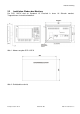
Betriebsanleitung 2.2 Installation /Einbau des Monitors Der SCD 1297-K wird als Standard 19” Einschub in einen 19“ Schrank montiert. Trageschienen sind nicht erforderlich. Abb. 1: Abmessung des SCD 1297-K Abb. 2: Schalttafelausschnitt Bedienpanel SCD 1297-K Seite 10 / 66 DOC-Nr.: b40010de1.
Betriebsanleitung Wärmeproblematik Um eine ausreichende Wärmeabgabe zu gewährleisten, sollte um das Gehäuse des SCD 1297-K die Luft frei strömen können. Weiterhin sollte gewährleistet sein, dass an dem Gehäuse eine Konvektion (Wärmeaustausch) stattfinden kann. Dies gilt insbesondere im Bereich der Rückwand des Systems. Bitte bedenken Sie, dass eine überhöhte Temperatur zum Defekt bzw. zur erheblichen Verkürzung der Lebensdauer des Monitors führen kann.
Betriebsanleitung 2.3.1 DVI-Schnittstelle X1 Die DVI-Schnittstelle ist mit einem 29-poligen DVI-Stecker realisiert. Pin 1 Signal TMDS-Data 2 - 2 TMDS-Data 2 + 3 TMDS-Data Shield 2 (GND) 4 - 5 - 6 DDC-CLK 7 DDC-DATA 8 Analogue V-Sync.
Betriebsanleitung 2.3.2 VGA-Schnittstelle X2 Die VGA-Schnittstelle ist mit einer Standard – 15-poligen HD-D-SUB-Buchse realisiert. Pin 2.3.3 Signal 1 Video Eingang Rot 2 Video Eingang Grün 3 Video Eingang Blau 4 Frei 5 Frei 6 GND (Rot) 5 7 GND (Grün)) 15 14 8 GND (Blau) 9 frei 10 GND 11 frei 12 frei 13 H-Sync. 14 V-Sync. 15 frei 4 10 3 9 13 2 8 12 1 7 11 6 Externe Tastatur X3 Rückseitig kann eine Standard PS2-Tastatur angeschlossen werden.
Betriebsanleitung 2.3.4 PC-Schnittstelle Tastatur X4 Diese Schnittstelle stellt die Tastaturverbindung mit dem Rechnersystem her und ist als Standard PS2-buchse ausgeführt. Zur Verbindung mit dem Rechnersystem kann ein Standard PS2-Kabel (Stecker-Stecker) mit einer Länge von maximal 5 m verwendet werden. Pin 2.3.
Betriebsanleitung 2.3.6 PC-Schnittstelle Tastatur/Maus (Long Distance ) X27 Diese Schnittstelle wird verwendet, wenn zwischen Bedienpanel und Rechnersystem größere Entfernungen (> 5 m) überbrückt werden müssen. Die Signale für Maus und Tastatur werden über ein gemeinsames Kabel übertragen. Als Verbindungskabel kann ein Standard CAT5/6/7 Ethernetkabel mit RJ45 Stecker verwendet werden.
Betriebsanleitung 2.3.8 Stromversorgung Die Stromversorgung des SCD 1297 erfolgt wahlweise über einen 12 VDC- oder24 VDCAnschluss. 2.3.8.1. Spannungsversorgung 12 VDC Der Anschluss ist eine 3,2 mm DC-Buchse. Pin Bezeichnung Beschreibung O GND Spannungseingang GND z +12V Spannungsversorgung +12 VDC 2.3.8.2. Spannungsversorgung 24 VDC Der Anschluss ist mit einer Phoenix Stecker ausgestattet. Pin Signal 2.
Betriebsanleitung Abb. 4: Verbindung des SCD 1297-K mit dem Rechnersystem bei geringen Distanzen Sind größere Distanzen zwischen Bedienpanel und Rechnersystem zu überbrücken oder befindet sich das Bedienpanel in einer Umgebung mit starken Störfeldern, so sollte die zweite Variante mit der speziellen Schnittstelle für Maus und Tastatur (Long Distance, X27) verwendet werden. Bei dieser Variante werden die Tastatur und Maussignale über ein Kabel übertragen.
Betriebsanleitung 2.5 Elektrische Inbetriebnahme Bevor Sie den SCD 1297-K an die Stromversorgung anschließen, sollte überprüft werden, ob die Stecker der Schnittstellen korrekt angesteckt und verschraubt sind. Wenn ein VGA-Signal am Bedienpanel anliegt, wird das Bild direkt auf dem Schirm dargestellt. 2.6 Inbetriebnahme der Tastatur/Maus In der Regel werden während des Startvorgangs eines Rechnersystem Tastatur und Maus überprüft und initialisiert.
Betriebsanleitung 3 Bedienung und Abgleich In diesem Kapitel wird die Funktion aller Bedien- und Abgleichelemente dargestellt. 3.1 Lage der Bedien- und Abgleichelemente Die Bedienelemente wie Tastatur und Maus sind von der Frontseite des Gerätes zugänglich. Bedienelemente zum Abgleich des Monitors sind von der Rückseite des Gerätes zugänglich. Die 4-Tasten zur OSD-Steuerung sind in der Abb. 1 auf Seite 10 ersichtlich.
Betriebsanleitung 3.2.1.1. Aufbau der Tastenzuordnungstabelle In der Tabelle werden verschiedene Schlüsselwörter, Zeichen und ein definierter Syntax verwendet. Die mitgelieferte Zuordnungstabelle beinhaltet alle Definitionen der Tasten die fest beschriftet sind. ; Tastentabelle Bedienpanel XXY an der Anlage ZYX ; #Name Simatictabelle 23 ; ;Grundebene, Ebene 0 ; X (0...11) Y (0...7) MF-II Key No.
Betriebsanleitung 3.2.1.3. Syntax eines Tabelleneintrages X Tastenkoordinate Y Tastenkoordinate Tastennummer Flag Kommentar Als Trennung zwischen den einzelnen Informationen wie X-Tastenkoordinate und YTastenkoordinate müssen Leerzeichen verwendet werden. Tastenkoordinate Diese Matrixkoordinate bestimmt die zu definierende Taste. Die Abb. 7 auf Seite 32 im Anhang zeigt alle Tasten des SCD 1297-K und deren Koordinaten. Tastennummer Die Tastennummer ist die einer äquivalenten MF2-Taste. In der Abb.
Betriebsanleitung 3.2.2 Programmierung der LEDs Die Folientastatur verfügt über 39 LED’s die in Kombination mit einigen Tasten angeordnet sind. Diese LED’s können z.B. als Quittungs- oder Freigabesignale dienen. Die Ansteuerung der LED’s erfolgt, wie auch die Programmierung der Tasten, über die Tastaturverbindung zwischen Rechner und Bedienpanel.
Betriebsanleitung Die Zuordnung der LED-Bytes B1-B5 zu dem jeweiligen LED: Byte LED Taste Beispiel Byte LED B1.0 LED40* B1.1 Taste B3.4 LED20 F4 LED39 Shift 0 ,B1L’ X 1 A = 0x41 B1.2 LED38 ACK 0 B3.6 LED18 F2 0 B1.3 LED37 Help X 1 B3.7 LED17 F1 X 1 B1.4 LED36 F20 B4.0 LED16 S16 B1.5 LED35 F19 X 1 ,B1H’ 0 1 = 0x31 B1.6 LED34 F18 B1.7 LED33 F17 B2.0 LED32 F16 B2.1 LED31 F15 B2.2 LED30 F14 B2.3 LED29 B2.4 B3.5 LED19 F3 Beispiel X 1 ,B3H’ X 1 B = 0x42 B4.
Betriebsanleitung 3.3 Integrierte Maus (Fingermaus) Die in der Frontplatte integrierte “Fingermaus” erfüllt die gleiche Funktion wie eine herkömmliche Microsoft kompatible 2-Tasten-Maus. Die Mausbewegung wird mit Hilfe des Mittleren Feldes der Maus durchgeführt. Das Feld ist in die gewünschte Bewegungsrichtung zu drücken. Die Druckstärke wirkt sich auf die Bewegungsgeschwindigkeit des Mauszeigers aus. Die beidseitig angeordneten Tasten entsprechen der Linken und Rechten Maustaste. 3.
Betriebsanleitung 3.4.2.1. Quick-OSD-Menü Die Tasten des Bedienelements und der externen Tastatur haben folgende Funktion.
Betriebsanleitung 3.4.2.2. OSD-Menü Die Tasten des Bedienelements haben folgende Funktion. Taste (+) (-) MENU MF2 Funktion(en) Cursor • Einstellparameterwert erhöhen rechts • Auswahl nach rechts Cursor • Einstellparameterwert erniedrigen links • Auswahl nach links • Ein-/Ausschalten Enter • OSD-Aufruf • SET Cursor • Up/Down Hauptmenü/Untermenü auswählen Punkte im Hauptmenü / Untermenü von oben nach unten durchgehen, auswählen Aufruf durch die Taste bzw.
Betriebsanleitung OSD-Menü-Funktionen (RGB) Hauptmenü Funktion Einstellen/Einstellwert/ Einstellbereich Beschreibung Bild 1 Helligkeit Einstellbereich: 0 bis 100 über Einstelltasten (+/-) Helligkeit einstellen Anpassen der Wiedergabe der hellen Bildpartien Kontrast Einstellbereich: 0 bis 100 über Einstelltasten (+/-) Kontrast einstellen Anpassen der Wiedergabe der dunklen Bildpartien H Position Einstellbereich: 0 bis 100 über Einstelltasten (+/-) Bild in horizontaler Richtung verschieben V-Po
Betriebsanleitung Hauptmenü Funktion Einstellen/Einstellwert/ Einstellbereich Beschreibung Optionen 2 DPMS EIN – AUS Display Power Management System (DPMS) ein- oder ausschalten. Ist das DPMS aktiviert, schaltet der Monitor ab, sobald keine Synchronisationssignale mehr anliegen d.h. der Bildschirm wird dunkel.
Betriebsanleitung Hauptmenü Funktion Einstellen/Einstellwert/ Einstellbereich Utilities Sprache Englisch – Deutsch Sprache für die Bedienung des OSD-Menüs auswählen Kalibration <+> drücken Abgleich des internen A/D-Wandlers (Menü-Führung folgen) Werkseinstellung <+> drücken Rücksetzen aller Funktionen wie Helligkeit, Kontrast, ... auf die Werkseinstellungen.
Betriebsanleitung 4 Technische Daten 4.1 Displaymodule Typ Aktives FarbTFT-LCD Diagonale 30,8 cm (12,1") Displayfläche (WxH) 246,0 x 184,5 mm Auflösung 800 x 600 Pixels Pixelblende 0,308 x 0,308 mm² Farben 262.144 Backlight 2 x CCFT (Cold Cathode Fluorescent Tube) Helligkeit (typisch) ca. 370 cd/m² Kontrast 450:1 Blickwinkel (typisch) 4.2 L/R 70° O/U 50°/60° Stromversorgung Eingangsspannung Limited power source max.
Betriebsanleitung 4.5 Gehäuse Gewicht ca. 4,5 kg Material Gehäuse Aluminium 4.6 Eingangssignal (Video) Pegel 0,7VSS RGB analog bei 75 Ω Bandbreite 140 MHz (-3 dB) Impedanz 75 Ω Synchronisation - Sep. Sync. (TTL) - Sync on green - Composite Sync H Frequenz 30 bis 97 kHz V Frequenz 50 bis 100 Hz 4.7 EU-Konformitätserklärung über EMV Produkt LCD-Monitor SCD 1297-KT Prüfgrundlagen EG-Rahmenrichtlinien No. 89/336/EWG No.
Betriebsanleitung Anhang SIEM ENS 5 Abb. 7: Tastaturmatrix Bedienpanel SCD 1297-K Seite 32 / 66 DOC-Nr.: b40010de1.
Bedienpanel SCD 1297-K ! 1 Seite 33 / 66 58 Strg 44 30 16 1 2 45 > < | 46 Alt S W 18 Y 3 ² A 31 " 2 § 3 60 32 F2 113 17 Q @ 112 110 ^ F1 ESC X 4 D 19 E 47 ³ 114 F3 33 $ 4 C 5 48 R V 6 % 5 34 F 20 115 F4 49 G 21 T 35 & 6 B 7 116 F5 50 Z H 22 F6 36 51 23 U 61 N 8 / 7 { 117 J F7 37 M 9 I 52 ( 8 [ 118 µ K 24 F8 38 ; , 10 L 25 O 53 ) 9 ] 119 39 : .
Operating instruction High Resolution 31 cm/12“ LCD-Control Panel SCD 1297-KT (33) Operating Instruction SCD 1297-K (33) (Rack 19") 6GF6240-7MB © Copyright Siemens AG Control panel SCD 1297-K Page 34 / 66 DOC-Nr.: b40010de1.
Operating instruction No part of this document may be reproduced or transmitted without express permission. Violations will result in prosecution. All Rights reserved. © 2006 All Rights reserved. Control panel SCD 1297-K Page 35 / 66 DOC-Nr.: b40010de1.
Operating instruction Contents 1 1.1 1.2 1.3 Overview ..............................................................................................................38 Layout of this handbook ........................................................................................39 Warnings and safety notes....................................................................................40 Instructions for handling assemblies susceptible to electrostatic shock ................41 2 General installation..
Operating instruction Figures Fig. 1: Dimensions of the SCD 1297-K ..............................................................................43 Fig. 2: Cut out control panel...............................................................................................43 Fig. 3: Location of the interfaces and alignment controls ...................................................44 Fig. 4: Connecting the SCD 1297-K to the computer system over a short distance ..........50 Fig.
Operating instruction 1 Overview The SCD 1297-K is a control panel for PC-compatible computer systems and can be used as a man machine interface (MMI) platform for a wide variety of visualization systems. Special interfaces make it possible to have the SCD 1297-K in a different location as the computer system. Ninety-four keys and a “finger mouse” are provided for software control and operation. The 94 keys can be individually configured.
Operating instruction 1.1 Layout of this handbook This handbook should be kept within reach while installing and operating the LCD-monitor. It has been laid out so that even inexperienced users can find the information they require. Chapters are clearly arranged according to subject. In detail, the chapters are arranged as follows: Chapter 1 Introduction This chapter provides a brief description of the SCD 1297-K, including its properties, application areas and special features.
Operating instruction 1.2 Warnings and safety notes Transport The LCD-monitor should only be transported in its original packaging to ensure it will be protected against shocks and rough handling. Setting up When installing the monitor, it should be noted whether any moisture (condensation) has entered the unit during transport or storage. Additional important installation information can be found in the “Technical Data” chapter.
Operating instruction 1.3 Instructions for handling assemblies susceptible to electrostatic shock Most of the assemblies within the SCD 1297-K LCD-monitor contain components which can be destroyed by electrostatic voltages. It is also possible for the assemblies to be damaged in such a way that total failure does not occur.
Operating instruction 2 General installation Preparations for installing the LCD-monitor include the following points: • Removal of all packaging • Checking of components for damage • Comparison of components received with those on the delivery note • Connection to the computer system and power supply • Building into your system, bearing in mind technical and ergonomic aspects 2.
Operating instruction 2.2 Installation of the monitor The SCD 1297-K is a 19” rack module and is mounted in a standard 19” cabinet. Guide rails are not necessary. Fig. 1: Dimensions of the SCD 1297-K Fig. 2: Cut out control panel Control panel SCD 1297-K Page 43 / 66 DOC-Nr.: b40010de1.
Operating instruction Thermal Problems In order that the SCD 1297-K maintains an optimum operating temperature while in use, air must be allowed to circulate freely around the enclosure. This is especially important for the rear of the unit. Convection current must be allowed to circulate around the enclosure Please bear in mind that increased temperatures can lead to defects and to a significant reduction in the lifetime of the monitor.
Operating instruction 2.3.1 DVI interface X1 The DVI interface is a 29-pin DVI-connector. Pin 1 Signal TMDS-Data 2 - 2 TMDS-Data 2 + 3 TMDS-Data Shield 2 (GND) 4 - 5 - 6 DDC-CLK 7 DDC-DATA 8 Analogue V-Sync.
Operating instruction 2.3.2 VGA interface X2 The VGA interface is a standard 15-pin male HD-D-type connector. Pin 2.3.3 Signal 1 Video Input RED 2 Video Input GREEN 3 Video Input BLUE 4 NC 5 NC 6 GND (RED) 5 7 GND (GREEN)) 15 14 8 GND (BLUE) 9 NC 10 GND 11 NC 12 NC 13 H-Sync. 14 V-Sync. 15 NC 4 10 3 9 13 2 8 12 1 7 11 6 External keyboard X3 A standard PS2 keyboard can be connected at the rear of the unit.
Operating instruction 2.3.4 PC interface keyboard X4 This interface provides the keyboard connection to the computer system and is a standard PS2 female connector. A standard PS2 cable (male-male) with a maximum length of 5m should be used to connect the unit with the computer system. Pin 2.3.5 Signal 1 Data 2 - 3 GND 4 +5V 5 CLK 6 - PC interface mouse X5 This interface provides the mouse connection to the computer system and is a standard PS2 female connector.
Operating instruction 2.3.6 PC interface keyboard/mouse (Long Distance) X27 This interface is used when the computer system and the control panel are separated by more than 5m. The mouse and keyboard signals are transmitted via a common cable. A standard CAT5/6/7 Ethernet cable with an RJ45 connector is used. If this interface is used the PC must have a corresponding receiver which can convert the incoming signals back to standard keyboard and mouse signals (see Fig. 5, page 50). Pin 2.3.
Operating instruction 2.3.8 Power supply It is also possible to use for the power supply the 12 VDC supply or 24 VDC connector 2.3.8.1. Power supply 12 VDC The connector is a 3.2 mm DC-female. Pin Signal Description O GND Input GND z +12V Input +12 VDC 2.3.8.2. Power supply 24 VDC The interface is equipped with Phoenix connector. Pin Signal 2.4 1 GND 2 NC 3 +24 VDC Connecting to the Computer System The monitor has been tested and set up at the factory.
Operating instruction Fig. 4: Connecting the SCD 1297-K to the computer system over a short distance If the control panel and the computer system are further apart or if there are strong interference fields in the vicinity then the second variation using the special interface (long distance, X27) should be used for the mouse and keyboard. Here, both mouse and keyboard signals are transmitted over one cable, a standard CAT 5/6/7 Ethernet cable (note the signal configuration). Fig.
Operating instruction 2.5 Electrical Installation Before applying power to the SCD 1297-K, check that all connectors are plugged in correctly and secured. If a VGA signal is present, a picture should appear immediately on the display. 2.6 Installing the Keyboard and Mouse When a computer starts up it usually checks and initializes the keyboard and mouse.
Operating instruction 3 Operation and Alignment This chapter contains a description of the operating and alignment functions. 3.1 Location of the Operation and Alignment Control The operating controls such as the keyboard and mouse are accessible from the front of the unit. Buttons for aligning the display are located on the rear of the unit. The location of the 4 keys for the OSD can be seen in Fig. 1, page 43. The display can also be aligned using an externally connected PS2 keyboard. 3.
Operating instruction 3.2.1.1. Key Definition Table Various keywords, characters and syntax are used in the table. The table, which is supplied with the control panel, contains definitions for all of the keys with permanent labels. ; Key table for control panel XXY at plant ZYX ; #Name Simatic table23 ; ; Basic level, level 0 ; X (0...11) 0 Y (0...7) MF-II Key No.
Operating instruction 3.2.1.3. Syntax of a table entry X key co-ordinate Y key co-ordinate Key number Flag Comment The individual entries like X key co-ordinate and Y key co-ordinate must be separated by a space. Key co-ordinates This matrix co-ordinate specifies the key to be defined. Fig. 7, page 65 in the appendix shows all the SCD 1297-K keys and their co-ordinates. Key number The key number refers to the equivalent MF2 key. Fig.
Operating instruction 3.2.2 Programming the LEDs The foil keyboard has 39 LEDs which are arranged in combination with some of the keys. These LEDs can be used, for example, as receipt or ready signals. The LEDs are switched via the keyboard connection between the computer and the control panel, in a similar manner to the programming of the keys. A special command has been implemented for driving the LEDs since, in the MF2 specification; there are only NumLock, CapsLock and ScrollLock LEDs.
Operating instruction The correlation between the LED bytes B1 – B5 and the individual LEDs is shown below: Byte LED Key Example Byte LED B1.0 LED40* B1.1 Key B3.4 LED20 F4 LED39 Shift 0 ,B1L’ X 1 A = 0x41 B1.2 LED38 ACK 0 B3.6 LED18 F2 0 B1.3 LED37 Help X 1 B3.7 LED17 F1 X 1 B1.4 LED36 F20 B4.0 LED16 S16 B1.5 LED35 F19 X 1 ,B1H’ 0 1 = 0x31 B1.6 LED34 F18 B1.7 LED33 F17 B2.0 LED32 F16 B2.1 LED31 F15 B2.2 LED30 F14 B2.3 LED29 B2.4 B3.
Operating instruction 3.3 Integrated Mouse (Finger-mouse) The “finger-mouse” on the front of the control panel fulfils the same function as a standard Microsoft-compatible 2-button mouse. The mouse is moved using the central positioning surface. The surface should be pressed in the desired direction. The degree of pressure applied translates to the speed at which the mouse moves. The buttons to either side correspond to the left and right mouse buttons. 3.
Operating instruction 3.4.2.1. Quick-OSD-Menu Function(s) of the control keys.
Operating instruction 3.4.2.2. OSD-Menu Function(s) of the control keys. Key Function (+) MF2 Cursor right (-) Cursor left • Decrease the parameter value, • Go to the left MENU Enter • Start OSD • Select the main menu/submenu SET • Increase the parameter value • Go to the right Cursor • Scroll down or select menu idem in main menu / submenu Up/Down Invoke via key or MF - Control panel SCD 1297-K Page 59 / 66 DOC-Nr.: b40010de1.
Operating instruction OSD-Menu-Function (RGB) Main menu Function Adjust function / value / range Description Picture 1 Brightness setting range: 0 to 100 through key (+/-) adjust brightness Contrast setting range: 0 to 100 through key (+/-) adjust contrast change contrast between dark and light colors H Position setting range: 0 to 100 through key (+/-) move picture in horizontal direction V-Position setting range : 0 to 100 through key (+/-) move picture in vertical direction Phase setti
Operating instruction Main menu Function Adjust function / value / range Description Option 2 DPMS ON – OFF Display Power Management System (DPMS) on or off If DMPS activated, the monitor is turn off (backlight) when a synch signal is left. The screen is dark. Source scan OFF – ON – Standard Standard: ON Note: To scan new video source is not relevant because the monitor has one RGB input source only.
Operating instruction Main menu Function Adjust function / value / range Description Utilities Language English – German OSD language Calibration <+> press Adjustment of the internal A/D converter (following the menu instruction) Factory reset <+> press Reset of values like brightness, contrast,.. to default values Installation RGBMode <+> press Enter a new timing which is not in the internal timing table.
Operating instruction 4 Technical Data 4.1 Display module Type Active color TFT-LCD Diagonal 30.8 cm (12.1") Display area (WxH) 246.0 x 184.5 mm Resolution 800 x 600 Pixels Pitch 0.308 x 0.308 mm² Colors 262,144 Backlight 2 x CCFT (Cold Cathode Fluorescent Tube) Brightness (typical) approx. 370 cd/m² Contrast 450:1 Viewing angle (typical) 4.2 L/R 70° T/B 50°/60° Power supply Input voltage Limited power source max.
Operating instruction 4.5 Enclosure Weight approx. 4.5 kg Enclosure material Aluminum 4.6 Input signal (Video) Level 0.7VSS RGB analog at 75 Ω Band width 140 MHz (-3 dB) Impedance 75 Ω Synchronization - Sep. Sync. (TTL) - Sync on green - Composite Sync H- Frequency 30 to 97 kHz V- Frequency 50 to 100 Hz 4.7 EU Declaration of Conformity on EMC Product LCD-Monitor SCD 1297-KT Test foundation EU framework guidelines No. 89/336/EWG No.
Operating instruction Appendix SIEM ENS 5 Fig. 7: Keyboard matrix Control panel SCD 1297-K Page 65 / 66 DOC-Nr.: b40010de1.
Control panel SCD 1297-K ! 1 Page 66 / 66 58 Strg 44 30 16 1 2 45 > < | 46 Alt S W A Y 3 ² 18 31 " 2 § 3 60 32 F2 113 17 Q @ 112 110 ^ F1 ESC X 4 D 19 E 47 ³ 114 F3 33 $ 4 C 5 48 R V 6 % 5 34 F 20 115 F4 49 G 21 T 35 & 6 F5 B 7 116 50 Z H 22 F6 36 51 23 U 61 N 8 / 7 { 117 J F7 37 M 9 I 52 ( 8 [ 118 µ K 24 F8 38 ; , 10 L 25 O 53 ) 9 ] 119 39 : .