
Operating instructions

66/126
Siemens Building Technologies SED2 variable speed drives CM1U5192en
HVAC Products Programming 01.2002
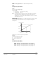
Torque [Nm]
Frequency [Hz]
Threshold frequency 1 Threshold frequency 3
Threshold frequency 2
P2182 P2184
P2183
P2189
Upper torque threshold 3
P2190 unterer
Lower torque threshold 3
P2187
Upper torque threshold 2
P2188
Lower torque threshold 2
P2185
Upper torque threshold 1
P2186
Lower torque threshold 1
5192D01en
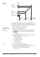
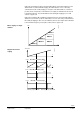
The permissible frequency/torque area is defined by the zone shaded gray. The
frequency limit values 1 to 3 define the areas used to compare the actual torque to the
preset torque. Nine parameters define torque monitoring. Parameters (P2182 to P2184)
define the frequency limit values to be set. Parameters (P2185 to P2190) limit the
tolerance band compared to the present torque curve.
1. Frequency limit value parameter P2182 to P2184.
Setting the three frequency limit values:
The 3 frequency limit values F1;F2;F3 determine a reasonable division across the
required torque area. Set the values desired in the manual mode by pressing
buttons
and read and write down the corresponding torque values via
parameter r0031.
Factory setting: 5;30;50 Hz.
2. Set the desired reaction of drive belt failure detection via parameter P2181.
Possible settings for P2181:
0 Belt failure detection disabled (factory setting).
1 Warn low torque/speed.
2 Warn high torque/speed.
3 Warn high/low torque/speed.
4 Trip low torque/speed.
5 Trip high torque/speed.
6 Trip high/low torque/speed.
P2181 must be set before P2185 to P2190 (not to 0).
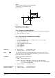
3. Set the torque limit value parameters P2185 to P2190 as follows:
Add
±15% to the torque derived from the setting of the frequency limit values to
define a permissible tolerance band for the torque values.
For allocation of variables, refer to the frequency/torque curve
.
Factory setting: 99999.0.
Frequency /
torque curve
Parameterizing belt
failure detection without
sensor
(commissioning)
Note