
Operating Instructions
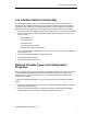
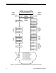
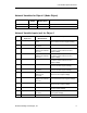
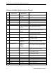
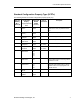
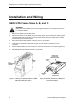
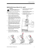
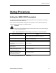
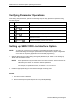
Table Of Contents
- Table of Contents
- Manual Organization
- Manual Notations
- Where To Send Comments
- Reference Documents
- General Description
- LON Interface Option Functionality
- Network Variable Types and Configuration Properties
- SED2 VFD Frame Sizes A, B, and C
- SED2 VFD Frame Sizes D, E, and F
- Installation and Wiring Notes
- Setting Up SED2 VFD Parameters
- Verifying Parameter Operations
- Setting up SED2 VFD LON Interface Option
- Status LED Functionality

SED2 VFD LON Interface Option Operating Instructions
Installation and Wiring
SED2 VFD Frame Sizes A, B, and C
WARNING:
Make sure that the SED2 VFD is de-energized (off) before you install or remove the
LON Interface Option.
1. Remove the SED2 VFD operator panel.
2. Install L
ON Interface on the SED2 VFD I/O module (Figure 4) by inserting two bottom guides
into appropriate slots at the sides of the I/O module and pushing the upper section inward
until the locking mechanism latches.
3. Route the network cable (without connector) to the L
ON Interface.
4. Terminate end of network cable with a single, two-pin, female LONWorks FTT-10A
connector.
5. Attach network cable FTT-10A connector to connector at bottom of Lon Interface (Figure 5).
6. Reinstall SED2 VFD operator panel on Lon Interface.
VFD0134R1
STATUS
LED
LON NETWORK
CONNECTION
SERVICE
PIN
CONNECTOR
TO SED2 VFD
OPERATOR PANEL
Figure 4. Installing LON Interface Option on SED2
VFD Frame Sizes A, B, and C.
Figure 5. Network Connection on Bottom of
L
ON Interface Option.
SED2
VFD
LON
INTERFACE
OPTION
8 Siemens Building Technologies