
Operating Instructions
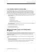
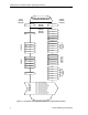
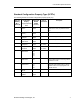
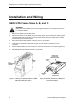
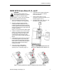
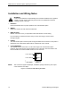
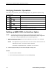
Table Of Contents
- Table of Contents
- Manual Organization
- Manual Notations
- Where To Send Comments
- Reference Documents
- General Description
- LON Interface Option Functionality
- Network Variable Types and Configuration Properties
- SED2 VFD Frame Sizes A, B, and C
- SED2 VFD Frame Sizes D, E, and F
- Installation and Wiring Notes
- Setting Up SED2 VFD Parameters
- Verifying Parameter Operations
- Setting up SED2 VFD LON Interface Option
- Status LED Functionality

SED2 VFD LON Interface Option Operating Instructions
Installation and Wiring Notes
WARNING:
A VFD can be switched on unintentionally if the serial bus installation is not operated
correctly. The bus must be started by personnel who are qualified and trained in
installing systems of this type.
1. DIP Switch
Leave DIP switches OFF for proper operation of the LON Interface Option.
2. WIRING
Wiring must conform to local codes and ordinances.
3. WIRE ROUTING
Maintain a minimum of 5 ft (1.5 m) between VFDs and network or sensor wiring.
If it is necessary for network and sensor wring to cross VFD wiring, it should cross at
90-degree angles.
4. POWER
The LON Interface Option receives power through its SED2 VFD connection. If VFD power is
switched off, the LON Interface Option will not communicate on the network.
5. L
ONTalk NETWORK
The LONTalk network connection is on the bottom edge of the LON Interface Option
(Figure 5). Figure 8 shows the wiring schematic for this connection. See www.echelon.com
for more details on the network cable and the FTT-10A connector.
L
ON
T
ALK
TP/FT-10
L
ON
T
ALK
TP/FT-10
29 (P+)
30 (N -)
FIELD WIRING
L
ON
INTERFACE
TERMINALS
VFD0135R1
NOTE: This connection supports twisted pair, unshielded, polarity-insensitive, peer-to-peer
communications at 78 Kbps.
Figure 8. LON Interface Option Wiring Schematic.
10 Siemens Building Technologies