
Operating Instructions
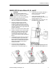
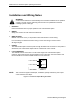

Table Of Contents
- Table of Contents
- Manual Organization
- Manual Notations
- Where To Send Comments
- Reference Documents
- General Description
- LON Interface Option Functionality
- Network Variable Types and Configuration Properties
- SED2 VFD Frame Sizes A, B, and C
- SED2 VFD Frame Sizes D, E, and F
- Installation and Wiring Notes
- Setting Up SED2 VFD Parameters
- Verifying Parameter Operations
- Setting up SED2 VFD LON Interface Option
- Status LED Functionality

Application Note using Ni 1000 Sensor Example
Application Note using Ni 1000
Sensor Example
Use the following parameter settings for PID loop control via the L
ON Interface Option.
Parameter and Setting Value of Parameter Explanation of Value
P2201, set to appropriate setting
for your installation.
Fixed PID setpoint in degrees
Celsius.
P2253[0], set to one of the
following:
• 755[0] for analog input 1 on
the drive.
• 2050[1] for nviDrvSpeedStpt.
• 2050[3] for setpoint nvi (nvi15
through nvi19).
Selection of setpoint source. L
ON-mapped setpoint.
P0701[0], set to 16. Local drive enable. Sets digital input 1 as the enable
for fixed setpoint PID.
P0756[1], set to 5.
Alternately set P0756[1] = 1
for 0 to 10V or
P0756[[1] = 3 for 4 to 20 mA.
Feedback input type for analog
input 2 (index 0 means analog
input 1, which is not used in fixed
setpoint applications).
Setting 5 is for Ni 1000 sensor
only.
P0757[1], set to appropriate
setting for your installation.
Low-end signal range, degrees
Celsius.
Input scaling.
P0758[1], set to appropriate
setting for your installation.
Low-end sensor range, degrees
Celsius.
Input scaling.
P0759[1], set to appropriate
setting for your installation.
High-end signal range, degrees
Celsius.
Input scaling.
P0760[1], set to appropriate
setting for your installation.
High-end sensor range, degrees
Celsius.
Input scaling.
Sensor Ranges. QAD21 = -30°C to 121°C
QAP22 = -25°C to 95°C
P2264[0], set to either 2050[2] for
feedback nvi (nvi10 through
nvi14) or 755[1] for analog
input 2.
PID feedback. L
ON-mapped feedback.
P2306, set to 1. Direct acting or reverse acting. 0 = Direct acting
1 = Reverse acting.
P2200, set to 1. Enable PID loop.
r0752[0] for analog input 1 or
r0752[1] for analog input 2.
Read only; check actual value.
Siemens Building Technologies 13