Climatix VFD User Guide A6V12384673 2021-04-23 Smart Infrastructure
Table of Contents Introduction ................................................................................................................................................................. 7 Overview ....................................................................................................................................................................... 7 Climatix VFD .............................................................................................................................
Descriptions of Parameter Settings ........................................................................................................................ 72 Descriptions of Parameter Settings ............................................................................................................................ 72 00 Drive Parameters......................................................................................................................................... 72 Description Group 01..........
Wiring Diagram ......................................................................................................................................................... 378 Failure Rate of the Drive Safety Function ................................................................................................................. 380 Reset the Parameter Settings ...................................................................................................................................
Option Card Mounting Position 1 ................................................................................................................... 432 Option Card Mounting Position 2 (Frame A to D) .......................................................................................... 433 Grounded installation ..................................................................................................................................... 436 RT-CAN-COMM ..............................................
Introduction Overview Introduction Overview This document is intended for Installers and Technicians using the Climatix VFD. The instructions in this document cover detailed features, functionality, and troubleshooting information for the Siemens Climatix VFD. For information on commissioning the Climatix VFD when used in the Climatix RTU Solution see the Climatix RT Remote Monitoring and Intelligent Diagnostics for Roof Top Controllers Start-Up (P/N A6V12053407).
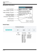
Introduction Nameplate Information Nameplate Information Model Name 8 | 443
Introduction Serial Number Serial Number 9 | 443
Introduction RFI Jumper RFI Jumper ● The drive contains Varistors/MOVs that are connected from phase-to-phase and from phase-to-ground to prevent the drive from unexpected stop or damage caused by mains surges or voltage spikes. Because the Varistor/MOVs from phase-to-ground are connected to ground with the RFI jumper, removing the RFI jumper disables the protection.
Introduction RFI Jumper ● Do not remove the RFI jumper while the power is on. ● Removing the RFI jumper also cuts the capacitor conductivity of the surge absorber to Ground and the built-in EMC filter capacitors. This voids compliance with the EMC specifications. ● To maintain the efficiency of the EMC circuit, do not remove the RFI jumper if the mains power is a symmetrically grounded power system. ● Remove the RFI jumper when conducting high voltage tests.
Introduction RFI Jumper Asymmetric Ground System (Corner Grounded TN Systems) CAUTION Do not remove the RFI jumper while power to the input terminal of the drive is ON. In the following four situations, you must remove the RFI jumper. This prevents the system from grounding through the RFI and filter capacitors and damaging the drive. You must remove the RFI jumper for an asymmetric ground system. 1. Grounding at a corner in a triangle configuration 2.
Specifications 115V Models Specifications 115V Models A Frame C Product Number RT0002-11N RT0005-11N RT01X-11N Applicable Motor Output [kW] 0.2 0.4 0.75 Applicable Motor Output [HP] 1/4 1/2 1 Outp ut Rated Output Capacity [kVA] 0.6 1.0 1.8 Rated Output Current [A] 1.6 2.5 4.8 Carrier Frequency [kHz] 2 to 15 (Default: 4) Rated Output Capacity [kVA] 0.7 1.0 2.1 Rated Output Current [A] 1.8 2.7 5.
Specifications 230V Models 230V Models A Frame B C Product Number RT0002-21F RT0005-21F RT0005-21F RT002X-21F RT003X-21F Applicable Motor Output [kW] 0.2 0.4 0.75 1.5 2.2 Applicable Motor Output [HP] 1/4 1/2 1 2 3 Output Heavy Duty Rated Output Capacity [kVA] 0.6 1.1 1.8 2.9 4.2 Rated Output Current [A] 1.6 2.8 4.8 7.5 11 Carrier Frequency [kHz] 2–15 (Default: 4) Rated Output Capacity [kVA] 0.7 1.2 1.9 3.2 4.8 Rated Output Current [A] 1.8 3.2 5 8.5 12.
Specifications 460V Models Weight (kg) 1.43 (0.65) 1.50 (0.68) Cooling Method Convective cooling EMC Filter Optional IP Rating IP20 1.79 (0.81) 2.31 (1.05) 2.73 (1.24) Fan cooling Table 3: 230V models three-phase. C Frame D E F Product Number RT005X-23N RT0075-23N RT010X-23N RT015X-23N RT020X-23N Applicable Motor Output [kW] 3.7/4 5.5 7.5 11 15 Applicable Motor Output [HP] 5 7.5 10 15 20 Outp ut Rated Output Capacity [kVA] 6.5 9.5 12.6 18.7 24.
Specifications 460V Models ut Input Duty Rated Output Current [A] 1.5 2.7 4.2 5.5 9 Normal Duty Rated Output Capacity [kVA] 1.4 2.3 3.5 5.0 8.0 Rated Output Current [A] 1.8 3 4.6 6.5 10.5 Rated Heavy Duty Input Current [A] Normal Duty 1.7 3.0 4.6 6.1 9.9 2.0 3.3 5.1 7.2 11.6 Rated Voltage/Frequency Three-phase 380 to 480 Vac (-15 to 10%), 50/60 Hz Mains Input Voltage Range [Vac] 323 to 528 Mains Frequency Range [Hz] 47 to 63 Weight lbs (kg) 1.68 (0.76) 1.79 (0.
Specifications 575V Models 575V Models A Frame B C D Product Number RT001X-53N RT002X-53N RT003X-53N RT005X-53N RT0075-53N RT010X-53N Applicable Motor Output [kW] 0.75 1.5 2.2 3.7 5.5 7.5 Applicable Motor Output [HP] 1 2 3 5 7.5 10 Outp Heavy ut Duty Rated Output Capacity [kVA] 1.7 3 4.2 6.6 9.9 12.2 Rated Output Current [A] 1.7 3 4.2 6.6 9.9 12.2 Carrier Frequency [kHz] 2 to 15 (Default: 4) Rated Output Capacity [kVA] 2.1 3.6 5 8 11.
Specifications Environment for Operation, Storage and Transportation Signal 4 to 20 mA / 0 to 10V 1 channel pulse input (33 kHz), 1 channel pulse output (33 kHz) Main Functions Multiple motor switching (a maximum of four independent motor parameter settings), Fast start-up, Deceleration Energy Back (DEB) function, Wobble frequency function, Fast deceleration function, Master and Auxiliary frequency source selectable, Restart after momentary power loss, Speed tracking, Over-torque detection, 16-step spee
Specifications Derating for Ambient Temperature, Altitude and Carrier Frequency Package Drop Storage/Transport ISTA procedure 1A (according to weight) IEC 60068-2-31 Vibration Operating .1.0 mm, peak to peak value range from 2–13.2 Hz; .0.7–2.0 G range from 13.2–55 Hz; .2.0 G range from 55–512 Hz. Compliance with IEC 60068-2-6 Non-operating 2.5 G peak, 5 Hz–2 kHz 0.
Specifications Derating for Ambient Temperature, Altitude and Carrier Frequency Current derating at ambient temperature Ambient temperature Operating altitude above sea level 104°F (40°C) 113°F (45°C) 0 to 3,280 ft (0–1000 m) 100% 3,284 to 4,921 ft (1001–1500 m) 4,924 to 6,561 ft (1501–2000 m) 100% 100% 95% 95% Table 8: For IP20/UL Open Type. Altitude Derating Curve Fig. 4: Altitude Derating Curve. Derating Curve for Carrier Frequency Normal load (Pr.00-16=0) 1. Space Vector Modulation Mode (Pr.
Specifications Derating for Ambient Temperature, Altitude and Carrier Frequency Fig. 5: Carrier Freq. (kHz) Ambient Temp. (Ta), 100% Load 2 3 4 5 6 7 8 9 10 11 12 13 14 15 50°C 100 96 86 77 69 62 56 51 46 42 38 35 32 29 40°C 100 100 100 90 82 74 68 62 56 52 48 44 40 37 35°C 100 100 100 96.5 88.5 80 74 67.5 61 57 53 48.5 44 41 1. Two-phase Modulation Mode (Pr.11-41=0) 2.
Specifications Derating for Ambient Temperature, Altitude and Carrier Frequency Carrier Freq. (kHz) Ambient Temp. (Ta), 100% Load 2 3 4 5 6 7 8 9 10 11 12 13 14 15 50°C 100 100 100 88 80 72 66 60 55 51 47 44 41 38 40°C 100 100 100 100 100 93 87 82 77 72 68 64 60 56 35°C 100 100 100 100 100 100 97.5 93 88 82.5 78.5 74 69.5 65 Heavy load (Pr.00-16=1) 1. Space Vector Modulation Mode (Pr.11-41=2) 2.
Specifications Derating for Ambient Temperature, Altitude and Carrier Frequency Fig. 8: Carrier Freq. (kHz) Ambient Temp. (Ta), 100% Load 2 3 4 5 6 7 8 9 10 11 12 13 14 15 50°C 100 100 100 100 100 93 86 80 74 69 65 61 57 53 40°C 100 100 100 100 100 100 100 95 89 83 78 73 69 65 35°C 100 100 100 100 100 100 100 100 96.5 90 84.
Digital Keypad Keyboard Panel Digital Keypad Keyboard Panel Descriptions of Keypad Functions Displayed items Descriptions Displays the present frequency setting for the drive. Displays the actual output frequency to the motor. ● Displays the user-defined output of a physical quantity. ● This example uses Pr.00-04=30 (user-defined output). Displays the load current. Forward command Reverse command Displays the count value. Displays a parameter item.
Digital Keypad Keypad Operation Process Displayed items Descriptions Displays a parameter value. Displays an external fault. Displays “End” for approximately one second if the data has been accepted and automatically stored in the register. Displays if the setting data is not accepted or data value exceeds the allowed range. Keypad Operation Process Main Page Selection Fig. 9: Fig. 10: Fig. 11: The digital keypad does not support parameter copy functions.
Digital Keypad Keypad Operation Process Fig. 12: General Mode 2 (The maximum operation frequency Pr.01-00 is in three decimal places. The example uses Pr.01-00 = 599.0 Hz.) Fig. 13: Application Macro Selection Page Go to Parameter Group 13 to set the application macro functions. The application macro function is enabled when Pr.13-00 ≠ 0. Once enabled, the Application Marco Selection page displays APP. If Pr.13-00 = 0, the APP page does not display. Fig. 14: Fig.
Digital Keypad Keypad Operation Process When Pr.13-00≠0, you enter into the APP page. After you press ENTER, the screen displays a corresponding short name according to Pr.13-00 setting values. Follow the process below to set the industry-specific application macro parameters. Example: When Pr.13-00 = 2, you enter into the APP page. After you press ENTER, the screen displays CoPr and the compressor application macro parameters are enabled.
Digital Keypad Keypad Operation Process Fig. 19: Use Pr.13-01–Pr.13-50 to set the user-defined parameters in sequence according to your requirement. The default setting 0.00 means there is no user-defined parameter. Press ENTER to set the corresponding parameters for Pr.13-01– Pr.13-50. The setting method of user-defined parameters is the same as that for non-user-defined parameters. You can use the Up and Down keys or left shift key to speed up the settings. Example: Setting Pr.
Digital Keypad Keypad Operation Process To remove a set user-defined parameter, remove from the last defined parameter (set to 0.00) first, or the display shows Err. For example, if there are five user-defined parameters (Pr.13-01, 13-02…13-05), to remove Pr.13-02, you must remove Pr.13-05 first, then 13-04, then 13-03, and then 13-02. Parameter setting D-1. Unsigned parameter (Parameter setting range ≥ 0; for example, Pr.
Digital Keypad Keypad Operation Process Without using the left shift key: Use the Up and Left/Down keys to select and adjust the parameters. Then, press ENTER to start the parameter settings. Using the left shift key: Long press MODE for two seconds until the last digit of the parameter value starts to blink. Increase the value by pressing the Up key. The value goes back to 0 after 9. Press the Left/Down key to shift the blinking cursor one digit to the left, and increase the value by pressing the Up key.
Summary of Parameter Settings Keypad Operation Process Summary of Parameter Settings This chapter provides a summary of parameter (Pr.) setting ranges and defaults. indicates the parameter can be set during operation.
Summary of Parameter Settings 00 Drive Parameters 00 Drive Parameters indicates the parameter can be set during operation. Pr. Explanation Settings Default 00-00 AC motor drive identity code 102: 115V, 1 Phase, 0.25 HP Read only 103: 115V, 1 Phase, 0.5 HP 104: 115V, 1 Phase, 1 HP 302: 230V, 1 Phase, 0.25 HP 303: 230V, 1 Phase, 0.5 HP 304: 230V, 1 Phase, 1 HP 305: 230V, 1 Phase, 2 HP 306: 230V, 1 Phase, 3 HP 202: 230V, 3 Phase, 0.25 HP 203: 230V, 3 Phase, 0.
Summary of Parameter Settings 00 Drive Parameters Pr. Explanation Settings Default 7: Reset CANopen Slave index 8: Keypad does not respond 9: Reset all parameters to defaults (base frequency is 50 Hz) 10: Reset all parameters to defaults (base frequency is 60 Hz) 11: Reset all parameters to defaults with base frequency at 50 Hz (keep the user-defined parameter values Pr.13-01–Pr.13-50) 12: Reset all parameters to defaults with base frequency at 60 Hz (keep the user-defined parameter values Pr.13-01–Pr.
Summary of Parameter Settings 00 Drive Parameters Pr. Explanation Settings Default 43: PID compensation (o.) (unit: %) 44: PID output frequency (b.) (unit: Hz) 46: Auxiliary frequency value (U.) (unit: Hz) 47: Master frequency value (A) (unit: Hz) 48: Frequency value after addition and subtraction of master and auxiliary frequency (L.) (unit: Hz) 51: PMSVC torque offset 58: Pr.00-05 User gain display (K) (Does not display decimal places.) 62: I2t (o.) (unit: %) 63: Error code (E.) 64: Warning code (n.
Summary of Parameter Settings 00 Drive Parameters Pr. Explanation Settings Default 00-21 Operation command source (AUTO, REMOTE) 0: Digital keypad 0 Note: HOA (Hand-Off-Auto) function is valid only when you use with MO function setting 42 and 56 or with KPC-CC01 (optional).
Summary of Parameter Settings 00 Drive Parameters Pr. Explanation Settings ● 01Cxh: psi ● 01Dxh: atm ● 01Exh: L/s ● 01Fxh: L/m ● 020xh: L/h ● 021xh: m3/s ● 022xh: m3/h ● 023xh: GPM ● 024xh: CFM Default xxxxh: Hz 00-26 Maximum user-defined value 0: Disable 0 0–65535 (when Pr.00-25 is set to no decimal place) 0.0–6553.5 (when Pr.00-25 is set to one decimal place) 0.00–655.35 (when Pr.00-25 is set to two decimal places) 0.000–65.535 (when Pr.
Summary of Parameter Settings 01 Basic Parameters Pr. Explanation Settings Default 4: External UP / DOWN key input (multi-function input terminals) 5: Pulse input without direction command (See Pr.
Summary of Parameter Settings 01 Basic Parameters Pr. Explanation Settings Default 01-11 Output frequency lower limit 0.00–599.00 Hz 0.00 01-12 Acceleration time 1 Pr.01-45 = 0: 0.00–600.00 sec. 10.00 Pr.01-45 = 1: 0.0–6000.0 sec. 10.0 Pr.01-45 = 0: 0.00–600.00 sec. 10.00 Pr.01-45 = 1: 0.0–6000.0 sec. 10.0 Pr.01-45 = 0: 0.00–600.00 sec. 10.00 Pr.01-45 = 1: 0.0–6000.0 sec. 10.0 Pr.01-45 = 0: 0.00–600.00 sec. 10.00 Pr.01-45 = 1: 0.0–6000.0 sec. 10.0 Pr.01-45 = 0: 0.00–600.00 sec.
Summary of Parameter Settings 01 Basic Parameters Pr. Explanation Settings Default Output voltage of motor 2 115V/230V models: 0.0–255.0V 220.0 (Base voltage / Motor’s rated voltage) 460V models: 0.0–510.0V 440.0 575V models: 0.0–637.0V 575.0 01-37 Mid-point frequency 1 of motor 2 0.00–599.00 Hz 3.00 01-38 Mid-point voltage 1 of motor 2 115V/230V models: 0.0–240.0 V 11.0 460V models: 0.0–480.0V 22.0 575V models: 0.0–600.0V 40.
Summary of Parameter Settings 02 Digital Input / Output Parameters Pr. Explanation Settings Default 01-57 Mid-point voltage 1 of motor 3 115V/230V models: 0.0–240.0 V 11.0 460V models: 0.0–480.0 V 22.0 575V models: 0.0–600.0 V 40.0 01-58 Mid-point frequency 2 of motor 3 0.00–599.00 Hz 1.50 01-59 Mid-point voltage 2 of motor 3 115V/230V models: 0.0–240.0 V 5.0 460V models: 0.0–480.0 V 10.0 575V models: 0.0–600.0 V 26.1 01-60 Minimum output frequency of motor 3 0.00–599.00 Hz 0.
Summary of Parameter Settings 02 Digital Input / Output Parameters Pr.
Summary of Parameter Settings 02 Digital Input / Output Parameters Pr. Explanation Settings Default 24: FWD JOG command 25: REV JOG command 26: TQC / FOC mode selection 27: ASR1 / ASR2 selection 28: Emergency stop (EF1) 29: Signal confirmation for Y-connection 30: Signal confirmation for ∆-connection 31: High torque bias (Pr.11-30) 32: Middle torque bias (Pr.11-31) 33: Low torque bias (Pr.
Summary of Parameter Settings 02 Digital Input / Output Parameters Pr. 02-17 Explanation Settings Default Multi-function output 3 (MO2) 2: Operation speed reached 0 3: Desired frequency reached 1 (Pr.02-22) 4: Desired frequency reached 2 (Pr.02-24) 5: Zero speed (Frequency command) 6: Zero speed including STOP (Frequency command) 7: Over-torque 1 (Pr.06-06–06-08) 8: Over-torque 2 (Pr.06-09–06-11) 9: Drive is ready 10: Low voltage warning (Lv) (Pr.
Summary of Parameter Settings 02 Digital Input / Output Parameters Pr. Explanation Settings Default 74: Over-torque 4 75: Forward RUN status 76: Reverse RUN status 02-18 Multi-function output direction 0000h–FFFFh (0: N.O.; 1: N.C.) 0000h 02-19 Terminal counting value reached (returns to 0) 0–65500 0 02-20 Preliminary counting value reached 0–65500 0 (does not return to 0) 02-21 Digital output gain (DFM) 1–55 1 02-22 Desired frequency reached 1 0.00–599.00 Hz 60.00 / 50.
Summary of Parameter Settings 03 Analog Input/Output Parameters Pr. Explanation Settings Default 02-80 Automatic positioning deceleration time 0.00: Disable the function 0.00 EF activates when the terminal count value reached 0: Terminal count value reached, no EF displays (continues to operate) Initial Frequency command (F) mode after stop 0: Use current Frequency command 02-81 02-82 0.01–100.00 sec.
Summary of Parameter Settings 03 Analog Input/Output Parameters Pr. Explanation Settings Default 03-11 Analog input gain (AVI) -500.0–500.0% 100.0 03-12 Analog input gain (ACI) -500.0–500.0% 100.0 03-15 Analog input filter time (AVI) 0.00–20.00 sec. 0.01 03-16 Analog input filter time (ACI) 0.00–20.00 sec. 0.
Summary of Parameter Settings 03 Analog Input/Output Parameters Pr. Explanation Settings Default 03-31 AFM output selection 0: 0 to 10V output 0 1: 0 to 20 mA output 2: 4 to 20 mA output 03-32 AFM DC output setting level 0.00 to 100.00% 0.00 03-35 AFM output filter time 0.00 to 20.00 sec. 0.01 03-39 VR input selection 0: Disable 1 1: Frequency command 03-40 VR input bias -100.0 to 100.0% 0.
Summary of Parameter Settings 04 Multi-step Speed Parameters Pr. Explanation Settings Default 03-70 Negative AVI proportional lowest point -100.00 to 100.00% (valid when Pr.03-28 sets as -10 to 10V) 0.00 03-71 Negative AVI voltage mid-point -10.00 to 0.00V (valid when Pr.03-28 sets as -10 to 10V) -5.00 03-72 Negative AVI proportional midpoint -100.00–100.00% -50.00 Negative AVI voltage highest point -10.00 to 0.00V Negative AVI proportional highest point -100.00 to 100.
Summary of Parameter Settings 05 Motor Parameters Pr.
Summary of Parameter Settings 05 Motor Parameters Pr. Explanation Settings Default 05-06 Stator resistance (Rs) for induction motor 1 0.000–65.535 Ω Depending on the model power 05-07 Rotor resistance (Rr) for induction 0.000–65.535 Ω motor 1 0.000 05-08 Magnetizing inductance (Lm) for induction motor 1 0.0–6553.5 mH 0.0 05-09 Stator inductance (Lx) for induction motor 1 0.0–6553.5 mH 0.
Summary of Parameter Settings 05 Motor Parameters Pr. Explanation Settings Default 05-28 Accumulated Watt-hour for a motor (W-hour) Read only 0.0 05-29 Accumulated Watt-hour for a motor in low word (kW-hour) Read only 0.0 05-30 Accumulated Watt-hour for a motor in high word (MW-hour) Read only 0.
Summary of Parameter Settings 06 Protection Parameters (1) Pr. Explanation Settings Default 05-70 Full-load current for induction motor 4 (A) 10–120% of the drive’s rated current Depending on the model power 05-71 Rated power for induction motor 4 0.00–655.
Summary of Parameter Settings 06 Protection Parameters (1) Pr.
Summary of Parameter Settings 06 Protection Parameters (1) Pr. Explanation Settings Default Fault record 9 (Pr.14-72) 10: Over-voltage at stop (ovS) 0 Fault record 10 (Pr.
Summary of Parameter Settings 06 Protection Parameters (1) Pr.
Summary of Parameter Settings 06 Protection Parameters (1) Pr. Explanation Settings Default o 06-36 IGBT temperature at malfunction -3276.7–3276.
Summary of Parameter Settings 07 Special Parameters Pr. Explanation Settings Default 06-66 Operation time of fault record 2 (Minutes) 0–1439 min. Read only 06-67 Operation time of fault record 3 (Days) 0 to 65535 days Read only 06-68 Operation time of fault record 3 (Minutes) 0 to 1439 min. Read only 06-69 Operation time of fault record 4 (Days) 0 to 65535 days Read only 06-70 Operation time of fault record 4 (Minutes) 0 to 1439 min. Read only 06-71 Low current setting level 0.
Summary of Parameter Settings 07 Special Parameters Pr. Explanation Settings Default 07-04 DC brake frequency at STOP 0.00 to 599.00 Hz 0.00 07-05 Voltage increasing gain 1 to 200% 100 07-06 Restart after momentary power loss 0: Stop operation 0 1: Speed tracking by the speed before the power loss 2: Speed tracking by the minimum output frequency 07-07 Allowed power loss duration 0.0 to 20.0 sec. 2.0 07-08 Base Block time 0.0 to 60.0 sec. 0.
Summary of Parameter Settings 07 Special Parameters Pr. Explanation Settings Default 07-22 Energy-saving gain 10 to 1000% 100 07-23 Automatic voltage regulation (AVR) function 0: Enable AVR 0 1: Disable AVR 2: Disable AVR during deceleration 07-24 Torque command filter time 0.001 to 10.000 sec. 0.050 0.001 to 10.000 sec. 0.100 Torque compensation gain (V/F and SVC control mode) IM: 0 to 10 (when Pr.05-33 = 0) 1 Slip compensation gain 0.00 to 10.
Summary of Parameter Settings 08 High-function PID Parameters Pr. Explanation Settings 07-73 Torque compensation gain (motor IM: 0 to 10 (when Pr.05-33 = 0) 3) PM: 0– to 000 (when Pr.05-33 = 1 or 2) 1 07-74 Slip compensation gain (motor 3) 0.00 0.00 to 10.00 Default (Default value is 1.00 in SVC mode) 07-75 Torque compensation gain (motor IM: 0 to 10 (when Pr.05-33 = 0) 4) PM: 0 to 5000 (when Pr.05-33 = 1 or 2) 1 07-76 Slip compensation gain 0.00 0.00 to 10.
Summary of Parameter Settings 08 High-function PID Parameters Pr. Explanation Settings Default 08-10 Sleep frequency 0.00 to 599.00 Hz 0.00 08-11 Wake-up frequency 0.00 to 599.00 Hz 0.00 08-12 Sleep time 0.0 to 6000.0 sec. 0.0 08-13 PID feedback signal error deviation level 1.0 to 50.0% 10.0 08-14 PID feedback signal error deviation detection time 0.1 to 300.0 sec. 5.0 08-15 PID feedback signal filter time 0.1 to 300.0 sec. 5.
Summary of Parameter Settings 09 Communication Parameters Pr. Explanation Settings Default 08-67 Master and auxiliary reverse running cutoff frequency 0.0 to 100.0% 10.0 08-68 PID deviation limit 0.00 to 100.00% 0.00 08-69 Integral separation level 0.00 to 100.00% 0.00 08-70 Smart start-up level 0.00 to 100.00% 5.00 08-71 Smart start-up frequency command 0.00 to 599.00 Hz 0.00 08-72 Smart start-up acceleration time 0.00–600.00 sec. 3.
Summary of Parameter Settings 09 Communication Parameters Pr. Explanation Settings Default 12: 8, N, 1 (RTU) 13: 8, N, 2 (RTU) 14: 8, E, 1 (RTU) 15: 8, O, 1 (RTU) 16: 8, E, 2 (RTU) 17: 8, O, 2 (RTU) 09-09 Communication response delay time 0.0 to 200.0 ms 2.0 09-10 Communication main frequency 0.00 to 599.00 Hz 60.
Summary of Parameter Settings 09 Communication Parameters Pr.
Summary of Parameter Settings 10 Speed Feedback Control Parameters Pr.
Summary of Parameter Settings 10 Speed Feedback Control Parameters Pr. Explanation Settings Default 10-04 Electrical gear at load side A1 1 to 65535 100 10-05 Electrical gear at motor side B1 1 to 65535 100 10-06 Electrical gear at load side A2 1 to 65535 100 10-07 Electrical gear at motor side B2 1 to 65535 100 10-10 Encoder stall level 0: No function 115 0 to 120% 10-11 Detection time of encoder stall 0.0 to 2.0 sec. 0.
Summary of Parameter Settings 11 Advanced Parameters Pr. Explanation Settings Default 10-42 Initial angle detection pulse value 0.0 to 3.0 1.0 10-49 Zero voltage time during start-up 0.000 to 60.000 sec. 0.000 10-51 Injection frequency 0 to 1200 Hz 500 10-52 Injection magnitude 115V / 230V models: 100.0V 15.0 460V models: 200.0V 30.0 575V models: 200.0V 37.5 Note: The setting range varies depending on the voltage.
Summary of Parameter Settings 11 Advanced Parameters Pr.
Summary of Parameter Settings 13 Industry Application Parameters 13 Industry Application Parameters indicates the parameter can be set during operation. Pr.
Summary of Parameter Settings 14 Protection Parameters (2) Pr. Explanation Settings Default 14-64 Output current at malfunction 5 0.00 to 655.35 Amp Read only 14-68 Output current at malfunction 6 0.00 to 655.35 Amp Read only 14-53 IGBT temperature at malfunction 2 -3276.7 to 3276.7oC Read only 14-57 IGBT temperature at malfunction 3 -3276.7 to 3276.7oC Read only 14-61 IGBT temperature at malfunction 4 -3276.7 to 3276.7oC Read only 14-65 IGBT temperature at malfunction 5 -3276.
Summary of Parameter Settings 14 Protection Parameters (2) Pr. Explanation Settings Default 14-80 Electronic thermal relay selection 3 (motor 3) 0: Inverter motor (with external forced cooling) 2 1: Standard motor (motor with the fan on the shaft) 2: Disable 14-82 Electronic thermal relay selection 4 (motor 4) 0: Inverter motor (with external forced cooling) 2 1: Standard motor (motor with the fan on the shaft) 2: Disable 14-81 Electronic thermal relay action time 3 (motor 3) 30.0 to 600.
Descriptions of Parameter Settings Descriptions of Parameter Settings Descriptions of Parameter Settings Descriptions of Parameter Settings 00 Drive Parameters indicates the parameter can be set during operation. ● ● Pr. Explanation Settings Default 00-00 AC motor drive identity code Read only #.# Pr. Explanation Settings Default 00-01 AC motor drive rated current display Read only #.# Pr.00-00 displays the AC motor drive identity code.
Descriptions of Parameter Settings Descriptions of Parameter Settings Models 460V Models: Three-phase A/B Frame C B D E F Power (kW) 0.4 0.75 1.5 2.2 3.7/4 5.5 7.5 11 15 18.5 22 Power (HP) 0.5 1 2 3 5 7.5 10 15 20 25 30 Identity Code 403 404 405 406 407 408 409 410 411 412 413 Rated Current for Heavy Duty 1.5 2.7 4.2 5.5 9 13 17 25 32 38 45 Rated Current for Normal Duty 1.8 3 4.6 6.5 10.5 15.7 20.5 28 36 41.
Descriptions of Parameter Settings Descriptions of Parameter Settings Pr. Explanation Settings Default 00-03 Start-up display 0: F (frequency command) 0 1: H (output frequency) 2: U (user-defined, see Pr.00-04) 3: A (output current) Determines the start-up display page after power is applied to the drive. The user-defined contents display according to the Pr.00-04 settings.
Descriptions of Parameter Settings Descriptions of Parameter Settings Pr. Explanation Settings Default 00-04 Content of multi-function display (user-defined) 0: Display output current (A) (unit: Amp) 3 1: Display counter value (c) (unit: CNT) 2: Display the drive’s actual output frequency (H.
Descriptions of Parameter Settings Descriptions of Parameter Settings Explanation 1 It can also display negative values when setting analog input bias (Pr.03-03–03-10). Example: Assume that AVI input voltage is 0V, Pr.03-03 is 10.0%, Pr.03-07 is 4 (Bias serves as the center). Explanation 2 Example: If MI1 and MI6 are ON, the following table shows the status of the terminals. Normally opened contact (N.O.
Descriptions of Parameter Settings Descriptions of Parameter Settings Pr. Explanation Settings Default 00-05 Coefficient gain in actual output frequency 0.00–160.00 1.00 Sets the user-defined unit coefficient gain. Set Pr.00-04 = 31 to display the calculation result on the screen (calculation = output frequency * Pr.00-05). Pr.
Descriptions of Parameter Settings Descriptions of Parameter Settings Fig. 21: Pr. Explanation Settings Default 00-10 Control mode 0: Speed Control mode 0 2: Torque mode Fig. 22: Determines the control mode of the AC motor drive. When Pr.00-10=2: Torque mode, control mode is IM TQC Sensorless. Pr.
Descriptions of Parameter Settings Descriptions of Parameter Settings If you use 1: IMVFPG control mode along with MI7 as speed feedback, you also need to set Pr.10-00=5 and Pr.1002=5. When Pr.00-10 = 0 and you set Pr.00-11 to 0, the V/F control diagram is as follows: Fig. 23: When Pr.00-10 = 0 and you set Pr.00-11 to 1, the V/F control + encoder diagram is as follows: Fig. 24: When Pr.00-10 = 0 and you set Pr.
Descriptions of Parameter Settings Descriptions of Parameter Settings Fig. 25: PM Space Vector Control (PMSVC): Fig. 26: When Pr.00-10=0 and you set Pr. 00-11 to 5, IMFOC Sensorless control diagram is as follows: Pr.
Descriptions of Parameter Settings Descriptions of Parameter Settings Fig. 27: Normal duty: overload rated output current 150% in 3 seconds. (120%, 1 minute). See Pr.00-17 for the setting for the carrier frequency. Refer to Chapter 9 Specifications or Pr.00-01 for the rated current. Heavy duty: overload rated output current 200% in 3 seconds. (150%,1 minute) See Pr.00-17 for the setting for the carrier frequency. See Chapter 9 Specifications or Pr. 00-01 for the rated current. Pr.
Descriptions of Parameter Settings Descriptions of Parameter Settings Fig. 28: From the table, you see that the PWM carrier frequency has significant influences on the electromagnetic noise, the AC motor drive heat dissipation, and the motor acoustic noise. Therefore, if the surrounding noise is greater than the motor noise, lower the carrier frequency to reduce the temperature rise. Although the motor has quiet operation in the higher carrier frequency, consider the entire wiring and interference.
Descriptions of Parameter Settings Descriptions of Parameter Settings Pr. Explanation Settings Default 00-21 Operation command source (AUTO, REMOTE) 0: Digital keypad 0 Note: HOA (Hand-Off-Auto) function is valid only when you use with MO function setting 42 and 56 or with KPC-CC01 (optional). 2: RS-485 communication input 1: External terminals 3: CANopen communication card 5: Communication card (does not include CANopen card) Determines the operation frequency source in the AUTO, REMOTE mode.
Descriptions of Parameter Settings Descriptions of Parameter Settings Pr. Explanation Settings Default 00-24 Digital operator (keypad) frequency command memory Read only Read only If the keypad is the frequency command source, when Lv or fault occurs, this parameter stores the current frequency command.
Descriptions of Parameter Settings Descriptions of Parameter Settings Pr.
Descriptions of Parameter Settings Descriptions of Parameter Settings bit 4–15: The displayed units for the control frequency F page, user-defined (Pr.00-04 = d10, PID feedback) and Pr.00-26. Fig. 30: You must convert the setting value to decimal when using the keypad to set parameters. Example: Assume that the user-defined unit is inWG and user-defined decimal place is the third decimal point.
Descriptions of Parameter Settings Descriptions of Parameter Settings Pr. Explanation Settings Default 00-29 LOCAL / REMOTE selection 0: Standard HOA function 0 1: When switching between local and remote, the drive stops. 2: When switching between local and remote, the drive runs with REMOTE settings for frequency and operating status. 3: When switching between local and remote, the drive runs with LOCAL settings for frequency and operating status.
Descriptions of Parameter Settings Descriptions of Parameter Settings In the HOA mode, if the multi-function input terminal (MI) function setting 41 and 42 are OFF, the drive does not receive any operation command and JOG is invalid. Pr. Explanation Settings Default 00-32 Digital keypad STOP function 0: STOP key disabled 0 1: STOP key enabled Valid when the operation command source is not the digital keypad (Pr.00-21≠ 0). When Pr.
Descriptions of Parameter Settings Descriptions of Parameter Settings Pr. Explanation Settings Default 00-49 Display filter time (keypad) 0.001–65.535 sec. 0.100 Minimizes the value fluctuation displayed by the digital keypad. Pr. Explanation Settings Default 00-50 Software version (date) Read only Read only Displays the current drive software version by date. Description Group 01 01 Basic Parameters indicates the parameter can be set during operation. Maximum Operation Frequency Pr.
Descriptions of Parameter Settings Descriptions of Parameter Settings Output Voltage Pr. Explanation Settings Default 01-02 Output voltage of motor 1 115V/230V models: 0.0–255.0V 220.0 (Base voltage/Motor’s rated voltage) 460V models: 0.0–510.0V 440.0 575V models: 0.0–637.0V 575.0 Output voltage of motor 2 115V/230V models: 0.0–255.0V 220.0 (Base voltage / Motor’s rated voltage) 460V models: 0.0–510.0V 440.0 575V models: 0.0–637.0V 575.0 Output voltage of motor 3 115V/230V models: 0.
Descriptions of Parameter Settings Descriptions of Parameter Settings Mid-point Frequency 2/ Mid-point Voltage 2 Pr. Explanation Settings Default 01-05 Mid-point frequency 2 of motor 1 0.00–599.00 Hz 1.50 01-06 Mid-point voltage 2 of motor 1 115V/230V models: 0.0–240.0 V 5.0 460V models: 0.0–480.0 V 10.0 575V models: 0.0–600.0 V 26.1 01-39 Mid-point frequency 2 of motor 2 0.00–599.00 Hz 1.50 01-40 Mid-point voltage 2 of motor 2 115V/230V models: 0.0–240.0V 5.0 460V models:0.0–480.
Descriptions of Parameter Settings Descriptions of Parameter Settings ● ● ● You usually set the V/F curve according to the motor’s allowable loading characteristics. Pay special attention to the motor’s heat dissipation, dynamic balance, and bearing lubrication when the loading characteristics exceed the loading limit of the motor.
Descriptions of Parameter Settings Descriptions of Parameter Settings Fig. 32: (2) For fan and hydraulic machinery Fig. 33: (3) High starting torque Start-up Frequency ● ● ● ● Pr. Explanation Settings Default 01-09 Start-up frequency 0.00–599.00 Hz 0.50 When the starting frequency (Pr.01-09) is larger than the Minimum Output Frequency of Motor 1 (Pr.01-07), the drive’s frequency output starts when the starting frequency (Pr.01-09) reaches the F command. See the following diagram for details.
Descriptions of Parameter Settings Descriptions of Parameter Settings Fig. 34: Output Frequency Pr. Explanation Settings Default 01-10 Output frequency upper limit 0.00–599.00 Hz 599.00 01-11 Output frequency lower limit 0.00–599.00 Hz 0.
Descriptions of Parameter Settings Descriptions of Parameter Settings ● ● ● ● Use the upper and lower limit output frequency settings to limit the actual output frequency. If the output frequency setting is higher than the upper limit (Pr.01-10), the drive runs with the upper limit frequency. If the output frequency setting is lower than the lower limit (Pr.01-11) but higher than the minimum output frequency (Pr.01-07), the drive runs with the lower limit frequency.
Descriptions of Parameter Settings Descriptions of Parameter Settings Acceleration / Deceleration Time Pr. Explanation Settings Default 01-12 Acceleration time 1 Pr.01-45 = 0: 0.00–600.00 sec. 10.00 Pr.01-45 = 1: 0.0–6000.0 sec. 10.0 Pr.01-45 = 0: 0.00–600.00 sec. 10.00 Pr.01-45 = 1: 0.0–6000.0 sec. 10.0 Pr.01-45 = 0: 0.00–600.00 sec. 10.00 Pr.01-45 = 1: 0.0–6000.0 sec. 10.0 Pr.01-45 = 0: 0.00–600.00 sec. 10.00 Pr.01-45 = 1: 0.0–6000.0 sec. 10.0 Pr.01-45 = 0: 0.00–600.00 sec. 10.
Descriptions of Parameter Settings Descriptions of Parameter Settings JOG Frequency Pr. Explanation Settings Default 01-22 JOG frequency 0.00–599.00 Hz 6.00 Fig. 36: You can use both the external terminal JOG and F1 key on the optional keypad KPC-CC01 (optional) to set the JOG function. When the JOG command is ON, the AC motor drive accelerates from 0 Hz to the JOG frequency (Pr.01-22). When the JOG command is OFF, the AC motor drive decelerates from the JOG frequency to stop.
Descriptions of Parameter Settings Descriptions of Parameter Settings S-curve for Acceleration / Deceleration Pr. Explanation Settings Default 01-24 S-curve for acceleration begin time 1 Pr.01-45 = 0: 0.00–25.00 sec. 0.20 Pr.01-45 = 1: 0.0–250.0 sec. 0.2 S-curve for acceleration arrival time 2 Pr.01-45 = 0: 0.00–25.00 sec. 0.20 Pr.01-45 = 1: 0.0–250.0 sec. 0.2 S-curve for deceleration begin time 1 Pr.01-45 = 0: 0.00–25.00 sec. 0.20 Pr.01-45 = 1: 0.0–250.0 sec. 0.
Descriptions of Parameter Settings Descriptions of Parameter Settings Skip Frequency ● ● ● ● Pr. Explanation Settings Default 01-28 Skip frequency 1 (upper limit) 0.00–599.00 Hz 0.00 01-29 Skip frequency 1 (lower limit) 0.00–599.00 Hz 0.00 01-30 Skip frequency 2 (upper limit) 0.00–599.00 Hz 0.00 01-31 Skip frequency 2 (lower limit) 0.00–599.00 Hz 0.00 01-32 Skip frequency 3 (upper limit) 0.00–599.00 Hz 0.00 01-33 Skip frequency 3 (lower limit) 0.00–599.00 Hz 0.
Descriptions of Parameter Settings Descriptions of Parameter Settings Fig. 38: ● ● ● ● ● When the drive’s Frequency command is lower than Fmin (Pr.01-07 and Pr.01-41), the drive operates according to this parameter. 0: the AC motor drive is in waiting mode without voltage output from terminals U, V, W. 1: the drive executes the DC brake by Vmin (Pr.01-08 and Pr.01-42) in V/F, FOC sensorless, and SVC modes. And it executes zero-speed operation in VFPG and FOCPG modes.
Descriptions of Parameter Settings Descriptions of Parameter Settings V/F Curve Selection Pr. Explanation Settings Default 01-43 V/F curve selection 0: V/F curve determined by Pr.01-00–Pr.01-08 0 1: V/F curve to the power of 1.5 2: V/F curve to the power of 2 Fig. 41: ● ● ● ● When setting to 0, see Pr.01-01–01-08 for the motor 1 V/F curve. For motor 2, see Pr.01-35–01-42. When setting to 1 or 2, the second and third voltage frequency settings (as shown in the V/F Curve diagram for Pr.
Descriptions of Parameter Settings Descriptions of Parameter Settings Auto-acceleration / Auto-deceleration Pr. Explanation Settings Default 01-44 Auto-acceleration and 0: Linear acceleration and deceleration 0 auto-deceleration setting 1: Auto-acceleration and linear deceleration 2: Linear acceleration and auto-deceleration 3: Auto-acceleration and auto- deceleration 4: Stall prevention by auto-acceleration and auto-deceleration (limited by Pr.01-12–Pr.
Descriptions of Parameter Settings Descriptions of Parameter Settings Time Parameters Pr. Explanation Settings Default 01-45 Time unit for acceleration / deceleration and S-curve 0: Unit 0.01 sec. 0 CANopen quick stop time Pr.01-45 = 0: 0.00–600.00 sec. 1.00 Pr.01-45 = 1: 0.0–6000.0 sec. 1.0 01-46 1: Unit 0.1 sec. Sets the time required to decelerate from the maximum operation frequency (Pr.01-00) to 0.00 Hz through the CANopen control. Regenerative Energy Restriction Control Method Pr.
Descriptions of Parameter Settings Descriptions of Parameter Settings Pr.
Descriptions of Parameter Settings Descriptions of Parameter Settings Pr.02-00 External Terminal Control Circuits Setting value: 1 Two-wire operation control FWD / STOP REV / STOP Setting value: 2 Two-wire operation control RUN / STOP FWD / REV Setting value: 3 Three-wire operation control Setting value: 4 Two-wire operation control Quick Start Setting value: 5 Two-wire operation control Quick Start Setting value: 6 Three-wire operation control Quick Start Pr.
Descriptions of Parameter Settings Descriptions of Parameter Settings Pr.
Descriptions of Parameter Settings Descriptions of Parameter Settings Pr. Explanation Settings Default 73: Force PID integral gain return to 0, disable integral 74: Reverse PID feedback 81: Simple positioning zero point position signal input 82: OOB loading balance detection 83: Multi-motor (IM) selection bit 0 84: Multi-motor (IM) selection bit 1 ● ● ● This parameter selects the functions for each multi-function terminal. When Pr.
Descriptions of Parameter Settings Descriptions of Parameter Settings Settings Functions 7 Acceleration / deceleration speed When you enable this function, the drive stops acceleration or deceleration immediately. inhibit After you disable this function, the AC motor drive starts to accelerate or decelerate from the inhibit point. 8 1st and 2nd acceleration / deceleration time selection 9 3rd and 4th acceleration / deceleration time selection 10 External Fault (EF) input (Pr.
Descriptions of Parameter Settings Descriptions of Parameter Settings Settings Functions Descriptions 13 Cancel the setting of autoacceleration / auto-deceleration time Set Pr.01-44 to one of the 01–04 setting modes before using this function. When this function is enabled, OFF is for auto mode and ON is for linear acceleration / deceleration. 15 Rotating speed command from AVI ON: force the source of the drive’s frequency to be AVI.
Descriptions of Parameter Settings Descriptions of Parameter Settings Settings Functions Descriptions 27 ASR1 / ASR2 selection ON: the speed is adjusted by the ASR 2 setting. OFF: the speed is adjusted by the ASR 1 setting. Refer to Pr.11-02 for details. 28 Emergency stop (EF1) ON: the output of the drive stops immediately, displays “EF1” on the keypad, and the motor is in free run status.
Descriptions of Parameter Settings Descriptions of Parameter Settings Settings Functions Descriptions 48 Mechanical gear ratio switch ON: the mechanical gear ratio switches to the second group. Refer to Pr.10-04–Pr.10-07 for details. 49 Enable drive When the drive is enabled, the RUN command is valid. When the drive is disabled, the RUN command is invalid. When the drive is operating, the motor coasts to stop. This function varies with MO = 45.
Descriptions of Parameter Settings Descriptions of Parameter Settings Settings Functions Descriptions 81 Simple positioning zero point position signal input Use this function as the trigger terminal for simple positioning with Pr.02-78–Pr.02-80. This function is just a simple positioning, so you must verify the positioning accuracy. Refer to Pr.02-80 for details.
Descriptions of Parameter Settings Descriptions of Parameter Settings Fig. 44: ● When Pr.02-09 is set to 1: The increasing or decreasing Frequency command (F) operates according to the setting of Pr.02-10 (0.001– 1.000 Hz/ms). ● When Pr.02-09 is set to 4: The tiered increasing or decreasing Frequency command (F) operates according to the setting of Pr.02-10 (0.001–1.000 Hz/100ms). Pr. Explanation Settings 02-11 Multi-function input response time 0.000–30.000 sec. Default 0.
Descriptions of Parameter Settings Descriptions of Parameter Settings ● ● ● ● ● ● ● Use this parameter to set the response time of the digital input terminals MI1–MI7. This function is to delay and confirm the digital input terminal signal. The time for delay is also the time for confirmation. The confirmation prevents interference that could cause error in the input to the digital terminals. But in the meanwhile, it delays the response time though confirmation improves accuracy. Pr.
Descriptions of Parameter Settings Descriptions of Parameter Settings Pr. Explanation Settings Default 02-13 Multi-function output 1 (RY1) 0: No function 11 02-16 Multi-function output 2 (MO1) 1: Indication during RUN 0 2: Operation speed reached 02-17 Multi-function output 3 (MO2) 3: Desired frequency reached 1 (Pr.02-22) 0 4: Desired frequency reached 2 (Pr.02-24) 5: Zero speed (Frequency command) 6: Zero speed including STOP (Frequency command) 7: Over-torque 1 (Pr.
Descriptions of Parameter Settings Descriptions of Parameter Settings Pr. Explanation Settings Default 67: Analog input level reached 68: SO output logic B 73: Over-torque 3 74: Over-torque 4 75: Forward RUN status 76: Reverse RUN status ● Use this parameter to set the function of multi-function terminals. Summary of Function Settings (Take the normally open contact (N.O.
Descriptions of Parameter Settings Descriptions of Parameter Settings Settings Functions Descriptions 20 Warning output Activates when a warning is detected. 21 Over-voltage Activates when over-voltage is detected. 22 Over-current stall prevention Activates when the over-current stall prevention is detected. 23 Over-voltage stall prevention Activates when over-voltage stall prevention is detected.
Descriptions of Parameter Settings Descriptions of Parameter Settings Settings Functions Descriptions 46 Master dEb output When dEb rises at the master, MO sends a dEb signal to the slave. Output the message when the master triggers dEb. This ensures that the slave also triggers dEb. Then the slave follows the deceleration time of the master to stop simultaneously with the master. 50 Output control for CANopen Control the multi-function output terminals through CANopen.
Descriptions of Parameter Settings Descriptions of Parameter Settings Settings Functions Descriptions 73 Over-torque 3 Activates when over-torque is detected. Pr.14-75 sets the over- torque detection level. Pr.14-76 sets the over-torque detection time (refer to Pr.14-74–14-76). 74 Over-torque 4 Activates when over-torque is detected. Pr.14-78 sets the over- torque detection level. Pr.14-79 sets the over-torque detection time (refer to Pr.14-77–14-79).
Descriptions of Parameter Settings Descriptions of Parameter Settings Pr. Explanation Settings Default 02-20 Preliminary counting value reached 0–65500 0 (does not return to 0) ● ● ● Use this parameter with Pr.02-19. When the count value counts from 1 to reach this value, the corresponding multi-function output terminal is activated (Pr.02-13, Pr.02-16, or Pr.02-17 is set to 17) and keeps counting to the last count value.
Descriptions of Parameter Settings Descriptions of Parameter Settings Fig. 47: ● ● ● ● Pr. Explanation Settings 02-34 Output frequency setting for multi- 0.00–599.00 Hz function output terminal (Motor speed when using PG Card) 0.00 02-58 Multi-function output terminal (function 42): brake frequency check point 0.00 0.00–599.00 Hz Default Use Pr.02-34 with Pr.02-58 for the crane function and select the crane function MO #42 to set the multi-function outputs Pr.02-13, Pr.02-16, and Pr.02-17.
Descriptions of Parameter Settings Descriptions of Parameter Settings Fig. 48: ● It is recommended that you use this with the Dwell acceleration/deceleration function as shown in the following diagram. Fig. 49: Pr.
Descriptions of Parameter Settings Descriptions of Parameter Settings Fig. 50: Pr. Explanation Settings Default 02-50 Display the status of multifunction input terminal Monitor the status of multi-function input terminals Read only Example: When Pr.02-50 displays 0034h (hex) (that is, the value is 52 (decimal) and 0110100 (binary)), it means that MI3, MI5 and MI6 are ON. Fig. 51: Pr.
Descriptions of Parameter Settings Descriptions of Parameter Settings Example: When Pr.02-51 displays 0009h (hex) (that is, the value is 9 (decimal) and 01001 (binary)), it means that Relay and MO1 are ON. Fig. 53: Pr. Explanation Settings 02-52 Display the external multi-function Monitor the status of PLC input terminals input terminals used by PLC Default Read only Fig. 54: Example: When Pr.
Descriptions of Parameter Settings Descriptions of Parameter Settings Fig. 56: Example: When Pr.02-53 displays 0009h (hex) (that is, the value is 9 (decimal) and 01001 (binary)), it means that Relay and MO1 are used by PLC. Fig. 57: Pr. Explanation Settings Default 02-54 Display the frequency command executed by external terminal 0.00–599.
Descriptions of Parameter Settings Descriptions of Parameter Settings Fig. 58: Pr. Explanation Settings Default 02-81 EF activates when the terminal count value reached 0: Terminal count value reached, no EF displays (continues to operate) 0 Initial Frequency command (F) mode after stop 0: Use current Frequency command 02-82 1: Terminal count value reached, EF activates 0 1: Use zero Frequency Command 2: Refer to Pr.02-83 to set up 02-83 Initial Frequency command (F) setting after stop 0.
Descriptions of Parameter Settings Descriptions of Parameter Settings Pr.
Descriptions of Parameter Settings Descriptions of Parameter Settings Using negative bias to set the frequency greatly reduces the noise interference. In a noisy environment, do NOT use signals less than 1 V to set the drive’s operation frequency. Pr. Explanation Settings Default 03-10 Reverse setting when analog signal input is negative frequency 0: Negative frequency input is not allowed. 0 The digital keypad or external terminal controls the forward and reverse direction.
Descriptions of Parameter Settings Descriptions of Parameter Settings Diagram 03 Diagram 04 129 | 443
Descriptions of Parameter Settings Descriptions of Parameter Settings Diagram 05 Diagram 06 130 | 443
Descriptions of Parameter Settings Descriptions of Parameter Settings Diagram 07 Diagram 08 131 | 443
Descriptions of Parameter Settings Descriptions of Parameter Settings Diagram 09 Diagram 10 132 | 443
Descriptions of Parameter Settings Descriptions of Parameter Settings Diagram 11 Diagram 12 133 | 443
Descriptions of Parameter Settings Descriptions of Parameter Settings Diagram 13 Diagram 14 134 | 443
Descriptions of Parameter Settings Descriptions of Parameter Settings Diagram 15 Diagram 16 135 | 443
Descriptions of Parameter Settings Descriptions of Parameter Settings Diagram 17 Diagram 18 136 | 443
Descriptions of Parameter Settings Descriptions of Parameter Settings Diagram 19 Diagram 20 137 | 443
Descriptions of Parameter Settings Descriptions of Parameter Settings Diagram 21 Diagram 22 138 | 443
Descriptions of Parameter Settings Descriptions of Parameter Settings Diagram 23 Diagram 24 139 | 443
Descriptions of Parameter Settings Descriptions of Parameter Settings Diagram 25 Diagram 26 140 | 443
Descriptions of Parameter Settings Descriptions of Parameter Settings Diagram 27 Diagram 28 141 | 443
Descriptions of Parameter Settings Descriptions of Parameter Settings Diagram 29 Diagram 30 142 | 443
Descriptions of Parameter Settings Descriptions of Parameter Settings Diagram 31 Diagram 32 143 | 443
Descriptions of Parameter Settings Descriptions of Parameter Settings Pr. Explanation Settings Default 03-11 Analog input gain (AVI) -500.0–500.0% 100.0 03-12 Analog input gain (ACI) -500.0–500.0% 100.0 Pr.03-03–03-12 are used when the Frequency command source is the analog voltage or current signal. ● ● Pr. Explanation Settings Default 03-15 Analog input filter time (AVI) 0.00–20.00 sec. 0.01 03-16 Analog input filter time (ACI) 0.00–20.00 sec. 0.
Descriptions of Parameter Settings Descriptions of Parameter Settings Fig. 59: Pr. Explanation Settings Default 03-19 Signal loss selection for analog input 4 to 20 mA 0: Disable 0 1: Continue operation at the last frequency 2: Decelerate to 0 Hz 3: Stop immediately and display ACE ● ● ● ● Determines the treatment when the 4–20 mA signal is lost (ACIc (Pr.03-29 = 0)). When Pr.03-29 ≠ 0, the voltage input to ACI terminal is 0–10 V or 0–20 mA, and Pr.03-19 is invalid.
Descriptions of Parameter Settings Descriptions of Parameter Settings Setting Function Description 15 Id feedback value (2.5 × rated current) is processed as 100%. 16 Vq-axis voltage command 230V series: 250V = 100% 460V series: 500V = 100% 575V series: 625V = 100% 17 Vd-axis voltage command 230V series: 250V = 100% 460V series: 500V = 100% 575V series: 625V = 100% 18 Torque command Motor rated torque = 100% 19 PG2 frequency command Maximum operation frequency (Pr.
Descriptions of Parameter Settings Descriptions of Parameter Settings Pr. Explanation Settings Default 03-27 AFM output bias -100.00 to 100.00% 0.00 ● Example 1: AFM 0–10 V is set to the output frequency, the output equation is ● Example 2: AFM 0–20 mA is set to the output frequency, the output equation is ● Example 3: AFM 4–20 mA is set to the output frequency, the output equation is ● ● This parameter sets the corresponding voltage of the analog output 0. Pr.
Descriptions of Parameter Settings Descriptions of Parameter Settings Pr. Explanation Settings Default 03-31 AFM output selection 0: 0 to 10V output 0 1: 0 to 20 mA output 2: 4 to 20 mA output 03-32 AFM DC output setting level 0.00 to 100.00% 0.00 03-35 AFM output filter time 0.00 to 20.00 sec. 0.01 03-39 VR input selection 0: Disable 1 1: Frequency command VR is the abbreviation for Variable Resistor; it is the potentiometer of the keyboard panel KPMS-LE01. Pr.
Descriptions of Parameter Settings Descriptions of Parameter Settings Pr. Explanation Settings Default 03-59 ACI mid-point Pr.03-29 = 1, 0.00 to 10.00V 12.00 Pr.03-29 ≠ 1, 0.00 to 20.00 mA 03-60 ACI proportional mid-point 0.00 to 100.00% 50.00 03-61 ACI highest point Pr.03-29 = 1, 0.00 to 10.00V 20.00 Pr.03-29 ≠ 1, 0.00 to 20.00 mA 03-62 ACI proportional highest point 0.00 to 100.00% 100.00 ● ● ● When Pr.03-29 = 1, the ACI setting is 0–10V and the unit is voltage (V). When Pr.
Descriptions of Parameter Settings Descriptions of Parameter Settings Pr. Explanation Settings Default 03-69 Negative AVI voltage lowest point -10.00 to 0.00V (valid when Pr.03-28 sets as -10 to 10V) 0.00 03-70 Negative AVI proportional lowest point -100.00 to 100.00% (valid when Pr.03-28 sets as -10 to 10V) 0.00 03-71 Negative AVI voltage mid-point -10.00 to 0.00V (valid when Pr.03-28 sets as -10 to 10V) -5.00 03-72 Negative AVI proportional midpoint -100.00–100.00% -50.
Descriptions of Parameter Settings Descriptions of Parameter Settings Pr. ● Settings Default 11 step speed frequency 0.00–599.00 Hz 0.00 04-11 12th step speed frequency 0.00–599.00 Hz 0.00 04-12 13th step speed frequency 04-14 ● ● ● th 04-10 04-13 ● Explanation 0.00–599.00 Hz 0.00 th 0.00–599.00 Hz 0.00 th 0.00–599.00 Hz 0.00 14 step speed frequency 15 step speed frequency Use the multi-function input terminals (refer to settings 1–4 of Pr.
Descriptions of Parameter Settings Descriptions of Parameter Settings Fig.
Descriptions of Parameter Settings Descriptions of Parameter Settings Fig. 63: Pr.
Descriptions of Parameter Settings Descriptions of Parameter Settings Pr. Explanation Settings Default 04-65 PLC buffer 15 0–65535 0 04-66 PLC buffer 16 0–65535 0 04-67 PLC buffer 17 0–65535 0 04-68 PLC buffer 18 0–65535 0 04-69 PLC buffer 19 0–65535 0 You can combine the PLC buffer with the built-in PLC function for a variety of applications. Description Group 05 05 Motor Parameters indicates the parameter can be set during operation.
Descriptions of Parameter Settings Descriptions of Parameter Settings Pr. Explanation Settings 05-03 Rated speed for induction motor 1 0–xxxxx rpm (Depending on the motor’s number of poles) (rpm) 1710 (60 Hz, 4 poles); 1410 (50 Hz, 4 poles) Default Depending on the motor’s number of poles Sets the rated speed for the motor as indicated on the motor nameplate. ● ● Pr.
Descriptions of Parameter Settings Descriptions of Parameter Settings Pr. Explanation Settings 05-15 Rated speed for induction motor 2 0–xxxxx rpm (Depending on the motor’s number of poles) (rpm) 1710 (60 Hz, 4 poles); 1410 (50 Hz, 4 poles) Default Depending on the motor’s number of poles Sets the rated speed for the motor as indicated on the motor nameplate. ● ● Pr.
Descriptions of Parameter Settings Descriptions of Parameter Settings ● ● ● ● ● You can apply Pr.05-23–Pr.05-25 in wide range motors, and the motor coil executes the Y-connection/∆connection switch as required. The wide range motors are related to the motor design. In general, the motor has higher torque with low speed Y-connection and has higher speed with high speed ∆-connection. Pr.05-24 enables and disables the switch of Y-connection/∆-connection. When you set Pr.05-24 to 1, the drive uses the Pr.
Descriptions of Parameter Settings Descriptions of Parameter Settings Fig. 66: ● ● ● Pr. Explanation Settings Default 05-26 Accumulated Watt-second for a motor in low word (W-msec.) Read only 0.0 05-27 Accumulated Watt-second for a motor in high word (W-sec.) Read only 0.0 05-28 Accumulated Watt-hour for a motor (W-hour) Read only 0.0 05-29 Accumulated Watt-hour for a motor in low word (kW-hour) Read only 0.
Descriptions of Parameter Settings Descriptions of Parameter Settings Pr. Explanation Settings Default 05-31 Accumulated motor operation time (minutes) 0–1439 0 05-32 Accumulated motor operation time (days) 0–65535 0 Use Pr.05-31 and Pr.05-32 to record the motor operation time. To clear the operation time, set Pr.05-31 and Pr.0532 to 0. An operation time shorter than 60 seconds is not recorded. Pr.
Descriptions of Parameter Settings Descriptions of Parameter Settings Pr. Explanation Settings 05-66 Rated speed for induction motor 3 0–xxxxx rpm (Depending on the motor’s number of poles) (rpm) 1710 (60 Hz, 4 poles); 1410 (50 Hz, 4 poles) Default Depending on the motor’s number of poles Sets the rated speed for the motor as indicated on the motor nameplate. ● ● Pr.
Descriptions of Parameter Settings Descriptions of Parameter Settings ● ● Pr. Explanation Settings Default 05-73 Number of poles for induction motor 4 2–20 4 Sets the number of poles for the motor (must be an even number). Set up Pr.01-63 and Pr.05-72 before setting up Pr.05-73 to make sure the motor operates normally. Pr. Explanation Settings Default 05-74 No-load current for induction motor 4 (A) 0.00–Pr.
Descriptions of Parameter Settings Descriptions of Parameter Settings Fig. 67: ● ● ● ● ● Pr. Explanation Settings 06-01 Over-voltage stall prevention 0: Disable Default 115V/230V models: 0.0 to 390.0 Vdc 380.0 460V models: 0.0 to 780.0 Vdc 760.0 575V models: 0.0 to 1000.0 Vdc 975.0 Setting Pr.06-01 to 0.0 disables the over-voltage stall prevention function (connected with braking unit or brake resistor). Use this setting when braking units or brake resistors are connected to the drive.
Descriptions of Parameter Settings Descriptions of Parameter Settings Fig. 68: ● When you set Pr.06-02 to 1 to use smart over-voltage stall prevention during deceleration, the drive maintains the DC bus voltage when decelerating and prevents the drive from OV. Fig. 69: ● ● ● ● When you enable the over-voltage stall prevention, the drive’s deceleration time is longer than the setting. If you encounter any problem with the deceleration time, see the following guides for troubleshooting.
Descriptions of Parameter Settings Descriptions of Parameter Settings Pr. Explanation Settings Default 06-03 Over-current stall prevention during acceleration Normal load: 0 to 150% 120 (100% corresponds to the rated current of the drive) Heavy load: 0 to 200% 180 (100% corresponds to the rated current of the drive) ● In heavy load (Pr.00-16=1), if the DC voltage is higher than the 875 VDC (575V series), 700 VDC (460V series) or 350 VDC (230 series), the maximum value for Pr.06-03 is 185%.
Descriptions of Parameter Settings Descriptions of Parameter Settings ● ● ● In heavy load (Pr.00-16=1), if the DC voltage is higher than the 875 VDC (575V series), 700 VDC (460V series) or 350 VDC (230 series), the maximum value for Pr.06-04 is 185%. This is a protection for the drive to decrease output frequency automatically when the motor overloads abruptly during constant motor operation. If the output current exceeds the setting value for Pr.
Descriptions of Parameter Settings Descriptions of Parameter Settings Pr.
Descriptions of Parameter Settings Descriptions of Parameter Settings Fig. 72: ● When you set Pr.06-06 or Pr.06-09 to 2 or 4, an ot1 / ot2 warning displays and the drive stops running after over-torque detection. The drive does not run until you manually reset it. Pr.
Descriptions of Parameter Settings Descriptions of Parameter Settings ● ● ● ● action of electronic thermal relays remains stable in low speed to ensure the load capability of the motor in low speed. Setting the parameter to 1 is suitable for standard motor (motor fan is fixed on the rotor shaft). For this kind of motor, the cooling capacity is lower in low speed; therefore, the action of an electronic thermal relay reduces the action time to ensure the life of motor.
Descriptions of Parameter Settings Descriptions of Parameter Settings Fig. 74: ● ● ● Pr. Explanation Settings Default 06-15 Temperature level overheat (OH) warning 32.0 to 212.0°F (0.0 to 110.0°C) Depending on the model power Sets the drive’s internal IGBT overheat warning level. When the temperature is higher than Pr.06-15 setting, the oH1 fault displays and the warning remains but it does not affect the drive operation.
Descriptions of Parameter Settings Descriptions of Parameter Settings Pr. ● ● ● ● Explanation Settings Default Fault record 8 (Pr.14-71) 0 Fault record 9 (Pr.14-72) 0 Fault record 10 (Pr.14-73) 0 The parameters record when the fault occurs and forces a stop. When low-voltage at stop fault (LvS) occurs, the fault is not recorded. When low-voltage during operation faults (LvA, Lvd, Lvn) occur, the faults are recorded.
Descriptions of Parameter Settings Descriptions of Parameter Settings 22: Electronics thermal relay 1 protection (EoL1) ● 23: Electronics thermal relay 2 protection (EoL2) ● 24: Motor PTC overheating (oH3) ● 26: Over torque 1 (ot1) ● 27: Over torque 2 (ot2) ● 28: Under current (uC) ● 31: EEPROM read error (cF2) ● 33: U-phase error (cd1) ● 34: V-phase error (cd2) ● 35: W-phase error (cd3) ● 36: cc (current clamp) hardware error (Hd0) ● 37: oc (over-current) hardware error (Hd1) ● 40:
Descriptions of Parameter Settings Descriptions of Parameter Settings ● 84: W-phase output phase loss (oPL3) ● 87: Low frequency overload protection (oL3) ● 89: Rotor position detection error (roPd) 101: CANopen guarding error (CGdE) ● 102: CANopen heartbeat error (CHbE) ● 104: CANopen bus off error (CbFE) ● 105: CANopen index error (CidE) ● 106: CANopen slave station setting error (CAdE) ● 107: CANopen index setting exceed limit (CFrE) ● 111: InrCOM time-out error (ictE) ● 121: Internal
Descriptions of Parameter Settings Descriptions of Parameter Settings ● When using the AVI terminal, you must set Pr.03-28 to 1 and switch AVI voltage to 0–10 V. At this time, the AVI input impedance is 20 KΩ. ● When the temperature reaches to the set protection level, the motor acts according to the settings for Pr.06-29 and displays warning “oH3” (if Pr.06-29 = 1–3). When the temperature is lower than the set protection level, you can press RESET key to clear the fault.
Descriptions of Parameter Settings Descriptions of Parameter Settings When a malfunction occurs, check the current Frequency command. If it happens again, it overwrites the previous record. Pr. Explanation Settings Default 06-32 Output frequency at malfunction 0.00 to 599.00 Hz Read only When a malfunction occurs, check the current output frequency. If it happens again, it overwrites the previous record. Pr. Explanation Settings Default 06-33 Output voltage at malfunction 0.0 to 6553.
Descriptions of Parameter Settings Descriptions of Parameter Settings Pr. Explanation Settings Default 06-42 Drive status at malfunction 0000h–FFFFh Read only When a malfunction occurs, check the current drive status (communication address 2101H). If it happens again, it overwrites the previous record. Pr. Explanation Settings Default 06-44 STO latch selection 0: STO latch 0 1: STO no latch ● ● ● Pr.06-44 = 0: STO Alarm Latch.
Descriptions of Parameter Settings Descriptions of Parameter Settings Fig. 77: ● Status 2: The drive is in STOP; Pr.06-48 = 0; Pr.07-02 ≠ 0 After the drive starts, the DC brake operates according to Pr.07-01 and Pr.07-02. During this period, OPHL detection is not active. After the DC brake action is completed, the drive starts to run, and enables the OPHL protection as mentioned above for status 1. Fig. 78: ● Status 3: The drive is in STOP; Pr.06-48 ≠ 0; Pr.
Descriptions of Parameter Settings Descriptions of Parameter Settings Fig. 79: Fig. 80: ● Status 4: The drive is in STOP; Pr.06-48 ≠ 0; Pr.07-02=0 When the drive starts, it executes Pr.06-48 as the DC brake. The DC brake current level is 20 times the Pr.0647 setting value. In this period, if an OPHL occurs within the time for Pr.06-48, the drive executes the Pr.06-45 setting after the drive starts counting for half the time of Pr.06-48.
Descriptions of Parameter Settings Descriptions of Parameter Settings Fig. 81: Fig.
Descriptions of Parameter Settings Descriptions of Parameter Settings Pr. Explanation Settings Default 06-49 LvX auto-reset 0: Disable 0 1: Enable 06-53 Input phase loss detection action (OrP) 0: Fault and ramp to stop 0 1: Fault and coast to stop The drive executes the input phase loss protection according to Pr.06-53. Pr.
Descriptions of Parameter Settings Descriptions of Parameter Settings ● ● The ambient temperature also affects the derating. See Section 9-7-1 Derating Curve for Ambient Temperature and Altitude. Take RT-005X-43N in normal load as an example: ambient temperature 50°C, UL open-type, and independent installation. When the carrier frequency is set to 10 kHz, it corresponds to 55% of the rated output current. If used for ambient temperature 60°C, it corresponds to 55% * 75% of the rated output current. Pr.
Descriptions of Parameter Settings Descriptions of Parameter Settings When using PT100, if the motor temperature is higher than 135°C (275°F), the drive starts to count the delay time for auto-deceleration (Pr.06-59). The drive decreases the motor frequency to the setting for Pr.06-58 when it reaches the delay time count value. The drive operates at the frequency set for Pr.06-58 until the motor temperature is lower than 135°C (275°F).
Descriptions of Parameter Settings Descriptions of Parameter Settings Pr. Explanation Settings Default 06-64 Operation time of fault record 1 (Minutes) 0 to 1439 min. Read only 06-66 Operation time of fault record 2 (Minutes) 0–1439 min. Read only 06-68 Operation time of fault record 3 (Minutes) 0 to 1439 min. Read only 06-70 Operation time of fault record 4 (Minutes) 0 to 1439 min. Read only 06-91 Operation time of fault record 5 (minutes) 0 to 1439 min.
Descriptions of Parameter Settings Descriptions of Parameter Settings Pr. Explanation Settings Default 06-71 Low current setting level 0.0 to 100.0% 0.0 06-72 Low current detection time 0.00 to 360.00 sec. 0.00 06-73 Low current action 0: No function 0 1: Fault and coast to stop 2: Fault and ramp to stop by the second deceleration time 3: Warn and continue operation The drive operates according to the setting for Pr.06-73 when the output current is lower than the setting for Pr.
Descriptions of Parameter Settings Descriptions of Parameter Settings Sets the level of the DC brake current output to the motor at start-up and stop. When setting the DC brake current, the rated current (Pr.00-01) is 100%. It is recommended that you start with a low DC brake current level and then increase until you reach the proper holding torque. However, the DC brake current cannot exceed the motor’s rated current to prevent the motor from burnout.
Descriptions of Parameter Settings Descriptions of Parameter Settings Pr. Explanation Settings Default 07-05 Voltage increasing gain 1 to 200% 100 When using speed tracking, adjust Pr.07-05 to slow down the increasing voltage gain if there are errors such as oL or oc; however, the speed tracking time will be longer. Pr.
Descriptions of Parameter Settings Descriptions of Parameter Settings Fig. 84: Fig.
Descriptions of Parameter Settings Descriptions of Parameter Settings Fig. 86: ● ● Pr. Explanation Settings Default 07-09 Current limit of speed tracking 20 to 200% 100 The AC motor drive executes speed tracking only when the output current is greater than the value set in Pr.0709. The maximum current for speed tracking affects the synchronous time. The larger the parameter setting, the faster the synchronization occurs.
Descriptions of Parameter Settings Descriptions of Parameter Settings Pr. Explanation Settings Default 07-12 Speed tracking during start-up 0: Disable 0 1: Speed tracking by the maximum output frequency 2: Speed tracking by the motor frequency at start-up 3: Speed tracking by the minimum output frequency ● ● Speed tracking is suitable for punch, fans and other large inertia loads. For example, a mechanical punch usually has a large inertia flywheel, and the general stop method is coast to stop.
Descriptions of Parameter Settings Descriptions of Parameter Settings Fig. 87: Situation 2: Momentary power loss, or too low and unstable power voltage, or power supply sliding down because of sudden heavy load Pr.
Descriptions of Parameter Settings Descriptions of Parameter Settings During the dEb deceleration (includes 0 Hz run), if the power recovers to a voltage higher than dEb return level, the drive maintains the frequency for three seconds and then accelerates again. The “dEb” warning on the keypad is automatically cleared. Fig. 88: Situation 3: Unexpected power shut down or power loss Pr.
Descriptions of Parameter Settings Descriptions of Parameter Settings Fig. 89: Situation 4: Unexpected power shut down or power loss Pr.07-13 = 2 and power does not recover The drive decelerates to 0 Hz. The DC bus voltage continues to decrease until the voltage is lower than the Lv level, and then the drive disconnects the soft start relay. The keypad displays “dEb” warning until the drive completely runs out of power. Situation 5: Pr.
Descriptions of Parameter Settings Descriptions of Parameter Settings The drive decelerates to 0 Hz. The DC bus voltage continues to decrease until the voltage is lower than the Lv level, and then the drive disconnects the soft start relay. The soft start relay closes again after the power recovers and the DC bus voltage is higher than the Lv return level. When the DC bus voltage is higher than the dEb return level, the drive maintains the frequency for three seconds and starts to accelerate linearly.
Descriptions of Parameter Settings Descriptions of Parameter Settings Pr. Explanation Settings Default 07-19 Fan cooling control 0: Fan is always ON 3 1: Fan is OFF after the AC motor drive stops for one minute. 2: Fan is ON when the AC motor drive runs, fan is OFF when the AC motor drive stops. 3: Fan turns ON when temperature (IGBT) reaches around 140°F (60°C). Use this parameter to control the fan. 0: Fan runs immediately when the drive power is turned ON.
Descriptions of Parameter Settings Descriptions of Parameter Settings Pr. Explanation Settings Default 07-23 Automatic voltage regulation (AVR) function 0: Enable AVR 0 1: Disable AVR 2: Disable AVR during deceleration The rated voltage of a 220V motor is usually 200 VAC, 60 Hz / 50 Hz, and the input voltage of the AC motor drive may vary from 180–264 VAC, 50 Hz / 60 Hz. Therefore, when the AC motor drive is used without the AVR function, the output voltage is the same as the input voltage.
Descriptions of Parameter Settings Descriptions of Parameter Settings Pr. Explanation Settings Default 07-26 Torque compensation gain (V/F and SVC control mode) IM: 0 to 10 (when Pr.05-33 = 0) 1 PM: 0 to 5000 (when Pr.05-33 = 1 or 2) 07-71 Torque compensation gain (motor IM: 0 to 10 (when Pr.05-33 = 0) 2) PM: 0 to 5000 (when Pr.05-33 = 1 or 2) 1 07-73 Torque compensation gain (motor IM: 0 to 10 (when Pr.05-33 = 0) 3) PM: 0– to 000 (when Pr.
Descriptions of Parameter Settings Descriptions of Parameter Settings This parameter is set to 1.00 automatically when Pr.00-11 (Speed Control Mode) is changed from V/F mode to vector mode. Otherwise, it is automatically set to 0.00. Apply the slip compensation after load and acceleration. Increase the compensation value from small to large gradually; add the output frequency to the [motor rated slip x Pr.07-27 (Slip Compensation Gain)] when the motor is at the rated load.
Descriptions of Parameter Settings Descriptions of Parameter Settings Pr. Explanation Settings Default 07-62 dEb gain (Kp) 0 to 65535 8000 07-63 dEb gain (Ki) 0 to 65535 150 Sets the PI gain of DC bus voltage controller when the dEb function activates. If the DC bus voltage drops too fast, or the speed oscillation occurs during deceleration after the dEb function activates, adjust Pr.07-62 and Pr.07-63.
Descriptions of Parameter Settings Descriptions of Parameter Settings Fig. 92: KP Proportional Gain (P), Ti Integral Time (I), Td Differential Time (D), S Calculation Concept of PID control: Proportional gain (P): The output is proportional to input. With only a proportional gain control, there is always a steady-state error. Integral time (I): The controller output is proportional to the integral of the controller input.
Descriptions of Parameter Settings Descriptions of Parameter Settings Fig. 93: Pr.00-04 = 10 (display PID feedback (b) (%)) Pr.01-12 Acceleration Time is set according to actual conditions. Pr.01-13 Deceleration Time is set according to actual conditions. Pr.00-21 = 0, operate through the digital keypad Pr.00-20 = 0, the digital keypad controls the setpoint. Pr.08-00 = 1 (negative PID feedback from analog input) ACI analog input Pr.03-01 = 5, PID feedback signal. Pr.
Descriptions of Parameter Settings Descriptions of Parameter Settings Use the integral controller to eliminate the deviation during stable system operation. The integral control does not stop working until the deviation is zero. The integral is affected by the integral time. The smaller the integral time, the stronger the integral action. It is helpful to reduce overshoot and oscillation for a stable system. Accordingly, the speed to lower the steady-state deviation decreases.
Descriptions of Parameter Settings Descriptions of Parameter Settings Pr. Explanation Settings Default 08-07 PID delay time 0.0 to 2.5 sec. 0.0 08-20 PID mode selection 0: Serial connection 0 1: Parallel connection 0: Use conventional PID control structure. 1: The proportional gain, integral gain and differential gain are independent. You can customize the P, I and D value to fit your application. Pr.08-07 determines the primary low pass filter time when in PID control.
Descriptions of Parameter Settings Descriptions of Parameter Settings Serial connection Parallel connection Fig. 94: Pr. Explanation Settings Default 08-08 Feedback signal detection time 0.0 to 3600.0 sec. 0.0 Valid only when the feedback signal is ACI (4–20 mA).
Descriptions of Parameter Settings Descriptions of Parameter Settings This parameter sets the detection time for abnormal PID signal feedback. You can also use it when the system feedback signal response is extremely slow. (Setting the detection time to 0.0 disables the detection function.) Pr.
Descriptions of Parameter Settings Descriptions of Parameter Settings Pr. Explanation Settings Default 08-16 PID compensation selection 0: Parameter setting 0 1: Analog input 0: The setting for Pr.08-17 gives the PID compensation value. Pr. Explanation Settings Default 08-17 PID compensation -100.0 to 100.0% 0 The PID compensation value = maximum PID target value × Pr.08-17. For example, if the maximum operation frequency Pr.01-00 = 60 Hz, and Pr.08-17 = 10.
Descriptions of Parameter Settings Descriptions of Parameter Settings wake-up delay time. When the drive reaches the wake-up delay time, it starts to catch up to reach the Frequency command value by the acceleration time. Fig. 95: 2) Internal PID Calculation Frequency Command (PID is in use, Pr.08-00 ≠ 0 and Pr.08-18=0.) When the PID calculation Frequency command reaches the sleep frequency, the drive starts to count the sleep time and the output frequency starts to decrease.
Descriptions of Parameter Settings Descriptions of Parameter Settings Fig. 96: 3) PID Feedback Value Percentage (PID is in use, Pr.08-00 ≠ 0 and Pr.08-18 = 1) When the PID feedback value reaches the sleep level percentage, the drive starts to count the sleep time and the output frequency starts to decrease. If the drive exceeds the preset sleep time, then the drive is in sleep mode (0 Hz).
Descriptions of Parameter Settings Descriptions of Parameter Settings Fig. 97: Pr. Explanation Settings Default 08-26 PID output command limit (reverse limit) 0.0 to 100.0% 100.0 When PID enables the reverse direction, the PID output is a negative value, and the PID output value is limited by the setting for Pr.08-26. Use this function with Pr.08-21. Pr. Explanation Settings Default 08-27 Acceleration/deceleration time for PID command 0.00 to 655.35 sec. 0.00 0.
Descriptions of Parameter Settings Descriptions of Parameter Settings Pr. Explanation Settings Default 08-29 Frequency base corresponding to 100.00% PID 0: PID control output 100.00% corresponding to maximum operation frequency (Pr.01-00) 0 1: PID control output 100.00% corresponding to the input value of the auxiliary frequency Valid only when you enable the master and auxiliary frequency functions. When Pr.08-29 = 0, PID control outputs 100.00% corresponding to the maximum operation frequency.
Descriptions of Parameter Settings Descriptions of Parameter Settings Fig. 98: When Pr.08-65≠0, the PID controller architecture shows as the diagram below: Fig. 99: When Pr.08-65 is not set to 0, Pr.00-20 is automatically set to 9. When Pr.08-65 is set to 1, set the PID command through Pr.08-66; when Pr.08-65 is not set to 1, Pr.08-66 displays the PID command. When Pr.08-65 is set to 2, 4, and 6, the corresponding communication address is C2003H. Pr.
Descriptions of Parameter Settings Descriptions of Parameter Settings In some cases, it is only possible for the PID to control the set point and the feedback to the same status when the PID output frequency is negative (the motor runs in reverse). However, an excessively high reverse frequency is not allowed in some cases, and Pr.08-67 is used to determine the upper limit of the reverse frequency Pr. Explanation Settings Default 08-68 PID deviation limit 0.00 to 100.00% 0.00 When Pr.
Descriptions of Parameter Settings Descriptions of Parameter Settings Fig. 100: Pr. Explanation Settings Default 08-75 PID2 parameter switch condition 0: No switching (see Pr.08-01–Pr.08-03) 0 1: Auto-switch based on the output frequency 2: Auto-switch based on the deviation 08-76 PID2 parameter switch deviation 1 0.00 to Pr.08-77% 10.00 08-77 PID2 parameter switch deviation 2 Pr.08-76 to 100.00% 40.
Descriptions of Parameter Settings Descriptions of Parameter Settings Fig. 101: Switch according to the deviation: When the deviation absolute value between the set point and feedback is smaller than Pr.08-76 (PID2 Parameter Switch Deviation 1), the first group PID parameters are used. When the deviation absolute value between the set point and feedback is larger than Pr.08-77 (PID2 Parameter Switch Deviation 2), the second group PID parameters are used.
Descriptions of Parameter Settings Descriptions of Parameter Settings Description Group 09 09 Communication Parameters indicates the parameter can be set during operation. When using the communication interface, the diagram on the right shows the communication port pin definitions. Pr. Explanation Settings Default 09-00 Communication address 1 to 254 1 Sets the communication address for the drive if the AC motor drive is controlled through RS-485 serial communication.
Descriptions of Parameter Settings Descriptions of Parameter Settings Pr.
Descriptions of Parameter Settings Descriptions of Parameter Settings Fig. 104: (7, O, 1) Fig. 105: 11-bit character frame (For RTU): (8, N, 2) Fig. 106: (8, E, 1) Fig. 107: (8, O, 1) Fig. 108: Communication Protocol 3.
Descriptions of Parameter Settings Descriptions of Parameter Settings DATA 0 n ≤ 16, maximum of 32 ASCII codes (20 sets of data) LRC Check High LRC checksum: LRC Check Low one 8-bit checksum consists of 2 ASCII codes END High End characters: END Low END High = CR (0DH), END Low = LF (0AH) RTU mode: START Defined by a silent interval of larger than/equal to 10 ms Address Communication address: 8-bit binary address Function Command code: 8-bit binary command DATA (n-1) Contents of data: …….
Descriptions of Parameter Settings Descriptions of Parameter Settings LRC Check END ‘2’ ‘0’ ‘D’ ‘0’ ‘7’ ‘0’ CR LRC Check ‘7’ ‘1’ LF END CR LF RTU mode: Command Message Response Message Address 01H Address 01H Function 03H Function 03H Starting data register 21H Number of register (count by byte) 04H Content of register address 2102H 17H Content of register address 2103H 00H CRC Check Low FEH CRC Check High 5CH 02H Number of register (count by world) 00H CRC Check Low 6
Descriptions of Parameter Settings Descriptions of Parameter Settings LRC Check ‘7’ LRC Check ‘1’ END CR ‘7’ ‘1’ END LF CR LF RTU mode: Command Message Response Message Address 01H Address 01H Function 06H Function 06H Target register 01H Target register 01H 00H Register content 17H 00H Register content 70H CRC Check Low CRC Check High 17H 70H 86H CRC Check Low 86H 22H CRC Check High 22H (3) 10H: Write multiple registers (can write at most 20 sets of data simultaneously).
Descriptions of Parameter Settings Descriptions of Parameter Settings ‘8’ The second data content ‘0’ ‘F’ ‘A’ ‘0’ LRC Check ‘9’ ‘A’ END CR LF RTU mode: Command Message Response Message ADR 01H ADR 01H CMD 10H CMD 1 10H Target register 05H Target register 05H 00H Number of register 00H 00H Number of register 00H (count by word) 02H (count by word) 02H Quantity of data (byte) 04 CRC Check Low 41H The first data content 13H CRC Check High 04H 88H The second data content 0
Descriptions of Parameter Settings Descriptions of Parameter Settings Step 6: Repeat step 2 through 5 for the next 8-bit byte of the command message. Continue doing this until all bytes are processed. The final contents of the CRC register are the CRC value. When transmitting the CRC value in the message, the upper and lower bytes of the CRC value must be swapped, that is, the lower order byte is transmitted first. The following is an example of CRC generation using C language.
Descriptions of Parameter Settings Descriptions of Parameter Settings bit 11–8 000B: Master speed 0001B: 1st step speed frequency 0010B: 2nd step speed frequency 0011B: 3rd step speed frequency 0100B: 4th step speed frequency 0101B: 5th step speed frequency 0110B: 6th step speed frequency 0111B: 7th step speed frequency 1000B: 8th step speed frequency 1001B: 9th step speed frequency 1010B: 10th step speed frequency 1011B: 11th step speed frequency 1100B: 12th step speed frequency 1101B: 13th step speed fr
Descriptions of Parameter Settings Descriptions of Parameter Settings 11B: REV running bit 8 1: Master frequency controlled by the communication interface bit 9 1: Master frequency controlled by the analog / external terminal signal bit 10 1: Operation command controlled by the communication interface bit 11 1: Parameter locked bit 12 1: Enable to copy parameters from keypad bit 15–13 Reserved 2102H Frequency command (XXX.XX Hz) 2103H Output frequency (XXX.
Descriptions of Parameter Settings Descriptions of Parameter Settings 2208H Display the positive / negative output torque estimated by the drive (+0.0: positive torque; -0.0: negative torque) (XXX.X%) 2209H Reserved 220AH Display the PID feedback value after enabling PID function (XXX.XX%) 220BH Display the AVI analog input terminal signal, 0–10 V corresponds to 0.00–100.00% (see Explanation 1 in Pr.00-04) 220CH Display the ACI analog input terminal signal, 4–20 mA / 0–10 V corresponds to 0.
Descriptions of Parameter Settings Descriptions of Parameter Settings 10b: Error bit 4 0b: Motor drive does not output 1b: Motor drive outputs bit 5 0b: No warning 1b: Warning 2227H Drive’s estimated output torque (positive or negative direction) (XXXX Nt-m) 2228H Reserved 2229H KWH display (XXXX.X) 222AH Reserved 222BH Reserved 222CH Reserved 222DH Reserved 222EH PID target value (XXX.XX %) 222FH PID offset (XXX.XX %) 2230H PID output frequency (XXX.
Descriptions of Parameter Settings Descriptions of Parameter Settings Exception Code Description 1 Function code is not supported or unrecognized. 2 Address is not supported or unrecognized. 3 Data is not correct or unrecognized. 4 Failure to execute this function code Pr. Explanation Settings Default 09-09 Communication response delay time 0.0 to 200.0 ms 2.
Descriptions of Parameter Settings Descriptions of Parameter Settings There is a group of block transfer parameters available in the AC motor drive (Pr.09-11–Pr.09-26). Using communication code 03H, you can store the parameters (Pr.09-11–Pr.09-26) that you want to read. Pr. Explanation Settings Default 09-30 Communication decoding method 0: Decoding method 1 1 1: Decoding method 2 EtherCAT card only supports decoding method 2 (60xx).
Descriptions of Parameter Settings Descriptions of Parameter Settings Pr.
Descriptions of Parameter Settings Descriptions of Parameter Settings Pr. Explanation Settings Default 09-76 Communication card IP address 1 0 to 255 (for Modbus TCP) 0 09-77 Communication card IP address 2 0 to 255 (for Modbus TCP) 0 09-78 Communication card IP address 3 0 to 255 (for Modbus TCP) 0 09-79 Communication card IP address 4 0 to 255 (for Modbus TCP) 0 Use Pr.09-76–Pr.09-79 with a communication card. Pr.
Descriptions of Parameter Settings Descriptions of Parameter Settings Description Group 10 10 Speed Feedback Control Parameters indicates the parameter can be set during operation. The following abbreviations are used in this parameter group: ● ASR: Adjust Speed Regulator ● PG: Pulse Generator Pr. Explanation Settings Default 10-00 Encoder type selection 0: Disabled 0 5: Pulse input (MI7) ● ● ● ● ● ● When you use MI7 single-phase pulse input, you must use it with Pr.00-20=4, Pr.10-00=0 and Pr.
Descriptions of Parameter Settings Descriptions of Parameter Settings Fig. 110: Pr. Explanation Settings Default 10-10 Encoder stall level 0: No function 115 0 to 120% Determines the maximum encoder feedback signal allowed before a fault occurs; the maximum operation frequency Pr.01-00 = 100%. Pr. Explanation Settings Default 10-11 Detection time of encoder stall 0.0 to 2.0 sec. 0.
Descriptions of Parameter Settings Descriptions of Parameter Settings Pr. Explanation Settings Default 10-16 Pulse input type setting 0: Disabled 0 5: Single-phase input (MI7) ● ● When Pr.10-16=5, you cannot set Pr.10-02 to 5: Single-phase input (MI7) for closed-loop control. The setting steps when using the MI7 single-phase pulse input as the frequency command: – Set Pr.00-20=4: Pulse input without direction command – Set Pr.10-00=5: Pulse input (MI7) – Set Pr.
Descriptions of Parameter Settings Descriptions of Parameter Settings Pr. Explanation Settings Default 10-25 FOC bandwidth for speed observer 20.0 to 100.0 Hz 40.0 Setting the speed observer to a higher bandwidth could shorten the speed response time but creates greater noise interference during the speed observation. ● ● ● Pr. Explanation Settings Default 10-26 FOC minimum stator frequency 0.0 to 10.0% fN 2.0 Sets the stator frequency lower limit in operation status.
Descriptions of Parameter Settings Descriptions of Parameter Settings ● ● ● ● ● ● ● ● ● ● Pr. Explanation Settings Default 10-32 PM FOC sensorless speed estimator bandwidth 0.00 to 600.00 Hz 5.00 Sets the speed estimator bandwidth. Adjust the parameter to influence the stability and the accuracy of the motor speed. If there is low frequency vibration (the waveform is similar to a sine wave) during the process, then increase the bandwidth.
Descriptions of Parameter Settings Descriptions of Parameter Settings ● ● ● ● ● ● ● ● ● ● ● ● If the switch point is too low and PM sensorless mode operates at a too low frequency, the motor does not generate enough back-EMF to let the speed estimator measure the right position and speed of the rotor, and causes stall and oc when running at the switch point frequency.
Descriptions of Parameter Settings Descriptions of Parameter Settings ● ● When the ratio of the salient pole (Lq / Ld) is lower, increase Pr.10-52 to make the angle detection accurate. Pr.10-52 is valid only when Pr.10-53 = 2. Pr. Explanation Settings Default 10-53 Angle detection method 0: Disabled 0 1: Force attracting the rotor to zero degrees 2: High frequency injection 3: Pulse injection Set to 2 for IPM; set to 3 for SPM. If these settings cause problems, then set the parameter to 1.
Descriptions of Parameter Settings Descriptions of Parameter Settings Power Setting Power Setting 1 HP 0.00023 10 HP 0.00358 2 HP 0.00043 15 HP 0.00743 3 HP 0.00083 20 HP 0.00953 5 HP 0.00148 25 HP 0.01428 7.5 HP 0.0026 30 HP 0.01765 Pr. Explanation Settings Default 11-02 ASR1/ASR2 switch frequency 5.00 to 599.00 Hz 7.00 Sets the low-speed and high-speed ASR switching point in the FOC area.
Descriptions of Parameter Settings Descriptions of Parameter Settings Fig. 111: Pr. Explanation Settings Default 11-13 PDFF gain value 0 to 200% 30 This parameter is invalid when Pr.05-24 = 1. This parameter is valid only when Pr.11-00 bit0 = 1. After you estimate and set Pr.11-00 bit0=1 (auto-tuning), use Pr.11-13 to reduce overshoot. However, a shift of the curve may occur earlier. In this case, you can set Pr.
Descriptions of Parameter Settings Descriptions of Parameter Settings A larger value improves resonance suppression function. The notch filter frequency is the mechanical frequency resonance. Pr. Explanation Settings Default 11-17 Forward motor torque limit 0 to 500% 500 11-18 Forward regenerative torque limit 0 to 500% 500 11-19 Reverse motor torque limit 0 to 500% 500 11-20 Reverse regenerative torque limit 0 to 500% 500 FOCPG and FOC Sensorless mode: The motor rated current = 100%.
Descriptions of Parameter Settings Descriptions of Parameter Settings Fig. 113: All control modes are based on 100% of the motor rated current except: IM: VF, VFPG, SVC PM: PMSVC Pr. Explanation Settings Default 11-21 Flux weakening curve for motor 1 gain value 0 to 200% 90 11-22 Flux weakening curve for motor 2 gain value 0 to 200% 90 Adjusts the output voltage for the flux weakening curve. For the spindle application, use this adjustment method: ● Run the motor to the highest frequency.
Descriptions of Parameter Settings Descriptions of Parameter Settings Pr. Explanation Settings Default 11-23 Flux weakening area speed response 0 to 150% 65 Controls the speed in the flux weakening area. The larger the value, the faster the acceleration/deceleration. In normal condition, you do not need to adjust this parameter. Pr. Explanation Settings Default 11-27 Maximum torque command 0 to 500% 100 Determines the upper limit of the torque command (motor rated torque is 100%).
Descriptions of Parameter Settings Descriptions of Parameter Settings Pr.11-32 Pr.11-31 Pr.11-30 Torque Offset MI = 33 (Low) MI = 32 (Mid) MI = 31 (High) OFF OFF OFF None OFF OFF ON Pr.11-30 OFF ON OFF Pr.11-31 OFF ON ON Pr.11-30 + Pr.11-31 ON OFF OFF Pr.11-32 ON OFF ON Pr.11-30 + Pr.11-32 ON ON OFF Pr.11-31 + Pr.11-32 ON ON ON Pr.11-30 + Pr.11-31 + Pr.11-32 Pr. Explanation Settings Default 11-29 Torque offset setting -100.0 to 100.0% 0.
Descriptions of Parameter Settings Descriptions of Parameter Settings P (W) value = Pr.05-02; ω (rad / s) value = Pr.05-03; RPM 2 = rad / s 60 Pr. Explanation Settings Default 11-33 Torque command source 0: Digital keypad 0 1: RS-485 communication (Pr.11-34) 2: Analog signal input (Pr.03-00) 3: CANopen 5: Communication Card RPM 2 = rad / s 60 Fig. 116: When Pr.11-33 is set to 0 or 1, you can set the torque command in Pr.11-34. When Pr.11-33 is set to 2, 3 or 5, Pr.
Descriptions of Parameter Settings Descriptions of Parameter Settings when the motor drives the load and the torque command is in the same direction as the speed limit, you can set the speed limit according to Pr.00-20. In torque control mode, the F page of keypad displays the present speed limit value. For details on the keypad display, refer to the LED Function Description in Section 7-14 Digital Keypad (optional). Fig. 117: Pr.
Descriptions of Parameter Settings Descriptions of Parameter Settings Two-phase modulation mode: effectively reduces the drive power component losses and provides better performance in long wiring applications. Space vector modulation mode: effectively reduces the power loss and electromagnetic noise of the motor. Pr. Explanation Settings Default 11-42 System control flag 0000–FFFFh 0000 bit No. Function 0 Reserved 1 FWD/REV action control Description 0: FWD/REV cannot be controlled by Pr.
Descriptions of Parameter Settings Descriptions of Parameter Settings 00-20 Master frequency command source (AUTO, REMOTE) 2 (External analog input) 00-21 Operation command source (AUTO, REMOTE) 1 (External terminals) 00-22 Stop method 0 (Ramp to stop) 00-23 Motor direction control 1 (Disable reverse) 01-00 Maximum operation frequency Default setting 01-01 Output frequency of motor 1 Default setting (Base frequency / Motor’s rated frequency) 01-02 Output voltage of motor 1 Default setti
Descriptions of Parameter Settings Descriptions of Parameter Settings 01-00 Maximum operation frequency Default setting 01-01 Output frequency of motor 1 (Base frequency / Motor’s rated frequency) Default setting 01-02 Output voltage of motor 1 (Base voltage / Motor’s rated voltage) Default setting 01-03 Mid-point frequency 1 of motor 1 Default setting 01-04 Mid-point voltage 1 of motor 1 Default setting 01-05 Mid-point frequency 2 of motor 1 Default setting 01-06 Mid-point voltage 2 of
Descriptions of Parameter Settings Descriptions of Parameter Settings 01-01 Output frequency of motor 1 (Base frequency / Motor’s rated frequency) Default setting 01-02 Output voltage of motor 1 (Base voltage / Motor’s rated voltage) Default setting 01-03 Mid-point frequency 1 of motor 1 Default setting 01-04 Mid-point voltage 1 of motor 1 Default setting 01-05 Mid-point frequency 2 of motor 1 Default setting 01-06 Mid-point voltage 2 of motor 1 Default setting 01-07 Minimum output frequ
Descriptions of Parameter Settings Descriptions of Parameter Settings Pr. Explanation Settings Default 14-50 Output frequency at malfunction 2 0.00 to 599.00 Hz Read only 14-54 Output frequency at malfunction 3 0.00 to 599.00 Hz Read only 14-58 Output frequency at malfunction 4 0.00 to 599.00 Hz Read only 14-62 Output frequency at malfunction 5 0.00 to 599.00 Hz Read only 14-66 Output frequency at malfunction 6 0.00 to 599.
Descriptions of Parameter Settings Descriptions of Parameter Settings Pr. Explanation Settings Default 14-70 Fault record 7 See fault record Pr.06-17–Pr.06-22 0 14-71 Fault record 8 See fault record Pr.06-17–Pr.06-22 0 14-72 Fault record 9 See fault record Pr.06-17–Pr.06-22 0 14-73 Fault record 10 See fault record Pr.06-17–Pr.
Descriptions of Parameter Settings Descriptions of Parameter Settings 27: Over-torque 2 (ot2) 28: Under current (uC) 31: EEPROM read error (cF2) 33: U-phase error (cd1) 34: V-phase error (cd2) 35: W-phase error (cd3) 36: cc (current clamp) hardware error (Hd0) 37: oc (over-current) hardware error (Hd1) 40: Auto-tuning error (AUE) 41: PID loss ACI (AFE) 43: PG feedback loss (PGF2) 44: PG feedback stall (PGF3) 45: PG slip error (PGF4) 48: ACI loss (ACE) 49: External fault (EF) 50: Emergency stop (EF1) 51: Ex
Descriptions of Parameter Settings Descriptions of Parameter Settings 77: STO Loss 2 (STL2) 78: STO Loss 3 (STL3) 79: U-phase over-current before run (Aoc) 80: V-phase over-current before run (boc) 81: W-phase over-current before run (coc) 82: Output phase loss U phase (oPL1) 83: Output phase loss V phase (oPL2) 84: Output phase loss W phase (oPL3) 87: Low frequency overload protection (oL3) 89: Rotor position detection error (roPd) 101: CANopen guarding error (CGdE) 102: CANopen heartbeat error (CHbE) 104
Descriptions of Parameter Settings Descriptions of Parameter Settings 142: Auto-tune error 1 (DC test stage) (AuE1) 143: Auto-tune error 2 (High frequency test stage) (AuE2) 144: Auto-tune error 3 (Rotary test stage) (AuE3) ● ● ● The parameters record when the fault occurs and forces a stop. When low voltage at stop fault (LvS) occurs, the fault is not recorded. When low-voltage during operation faults (LvA, Lvd, Lvn) occur, the faults are recorded.
Descriptions of Parameter Settings Descriptions of Parameter Settings When you set Pr.14-74 or Pr.14-77 to 2 or 4, an ot3/ot4 warning displays and the drive stops running after overtorque detection. The drive does not run until you manually reset it. Pr.
Descriptions of Parameter Settings Descriptions of Parameter Settings ● ● ● ● Setting the parameter to 1 is suitable for standard motor (motor fan is fixed on the rotor shaft). For this kind of motor, the cooling capacity is lower in low speed; therefore, the action of an electronic thermal relay reduces the action time to ensure the life of motor.
Descriptions of Parameter Settings Adjustment and Application Adjustment and Application Standard PM Synchronous AC Motor Adjustment Procedure Pr.00-11 Speed Control Mode = 2 SVC (Pr.
Descriptions of Parameter Settings Adjustment and Application PMSVC control diagram Fig. 118: Note: In the diagram, “PM motor” means “permanent magnet synchronous AC motor”. Adjustment procedure 1. Select PM synchronous AC motor control Pr.05-33 Induction Motor (IM) or Permanent Magnet (PM) Synchronous AC Motor Selection =1 (SPM) or 2 (IPM) 2. Set up motor parameters according to the motor’s nameplate – – – – – – Pr.01-01: Rated frequency Pr.01-02: Rated voltage Pr.05-34: Rated current Pr.
Descriptions of Parameter Settings Adjustment and Application Pr. Explanation Settings Default 05-00 Motor parameter 0: No function 0 auto-tuning 1: Dynamic test for induction motor (IM) 2: Static test for induction motor (IM) 5: Rolling auto-tuning for PM (IPM / SPM) 12: FOC sensorless inertia estimation 13: High frequency stall test for PM ● ● ● ● ● ● ● ● Set Pr.05-00 Motor Parameter Auto-tuning =13 (High frequency stall test for PM synchronous AC motor) and press RUN.
Descriptions of Parameter Settings Adjustment and Application Adjustment flow chart when starting WITHOUT load: 258 | 443
Descriptions of Parameter Settings Adjustment and Application Fig.
Descriptions of Parameter Settings Adjustment and Application Adjustment flow chart when starting WITH load: Fig.
Descriptions of Parameter Settings Adjustment and Application Pr. Explanation Settings Default 10-31 I/F mode, current command 0 to 150% rated current of the motor 40 Sets the current command for the drive in the low speed area (low speed area: Frequency command < Pr.10-39). When the motor stalls on heavy duty start-up or forward/reverse with load, increase the parameter value. If the inrush current is too high and causes oc stall, then decrease the parameter value.
Descriptions of Parameter Settings Adjustment and Application ● ● ● ● ● ● ● Pr. Explanation Settings Default 10-49 Zero voltage time during start-up 0.000 to 60.000 sec. 0.000 This parameter is valid only when the setting of Pr.07-12 (Speed Tracking during Start-up) = 0. When the motor is in static state at start-up, this increases the accuracy when estimating angles. In order to put the motor in static state, set the three-phase of the drive output to the motor to 0 V. The Pr.
Descriptions of Parameter Settings Adjustment and Application ● ● ● With a large motor load, a part of the drive output voltage is absorbed by the stator winding resistor; therefore, the air gap magnetic field is insufficient. This causes insufficient voltage at motor induction and results in excessive output current but insufficient output torque.
Warning Codes Digital Keypad RT-KEYPAD Warning Codes Digital Keypad RT-KEYPAD ID No. Display on LCD Keypad Warning Name 1 Description Communication error RS-485 Modbus illegal function code 1 (CE1) Action and Reset Action level When the function code is not 03, 06, 10 and 63 Action time Immediately act Warning setting parameter N/A Reset method Warning occurs when Pr.09-02=0 and the motor drive keeps running. The drive resets automatically when receiving the correct function code.
Warning Codes Digital Keypad RT-KEYPAD Incorrect communication command from upper unit Check if the communication command is correct. Malfunction caused by interference Verify the wiring and grounding of the communication circuit. It is recommended to separate the communication circuit from the main circuit, or wire in 90 degree for effective anti-interference performance. Different communication setting from the upper unit Check if the setting for Pr.
Warning Codes Digital Keypad RT-KEYPAD automatically when receiving the correct communication data value. Reset condition Immediately reset Record N/A Cause Corrective Actions Incorrect communication command from upper unit Check if the communication command is correct. Malfunction caused by interference Verify the wiring and grounding of the communication circuit.
Warning Codes Digital Keypad RT-KEYPAD ID No. Display on LCD Keypad 5 Warning Name Description Communication error 10 (CE10) RS-485 Modbus transmission time-out Action and Reset Action level When the communication time exceeds the detection time of Pr.09-03 communication time-out Action time Pr.09-03 Warning setting parameter N/A Reset method Warning occurs when Pr.09-02=0 and the motor drive keeps running. The drive resets automatically when receiving the next communication packet.
Warning Codes Digital Keypad RT-KEYPAD Cause Corrective Actions Communication connection error SE1: The causes of error are mostly communication problems between the keypad and control board. Potential causes include communication signal interference and the unacceptable communication command to the Slave. Keypad error Control board error Check if the error occurs randomly, or only occurs when copying certain parameters (the error displays on the upper right corner of the copy page).
Warning Codes Digital Keypad RT-KEYPAD Cause Corrective Actions Check if the ambient temperature or Check the ambient temperature. temperature inside the cabinet is too high, Regularly inspect the ventilation hole of the control cabinet. or if there is obstruction in the ventilation Change the installed place if there are heating objects, such as brake resistors, in the hole of the control cabinet. surroundings. Install/ add cooling fan or air conditioner to lower the temperature inside the cabinet.
Warning Codes Digital Keypad RT-KEYPAD ID No. Display on LCD Keypad 12 Warning Name Description ACI analog signal loss (AnL) Analog input current loss (including all analog 4–20 mA signals) Action and Reset Action level When the analog input is lower than 4 mA (only detects analog input 4–20 mA) Action time Immediately act Warning setting parameter Pr.
Warning Codes Digital Keypad RT-KEYPAD Cause Corrective Actions Broken motor cable Exclude the connection issue of the motor and its load. Improper setting for the low current protection Set the proper settings for Pr.06-71, Pr.06-72 and Pr.06-73. Low load Check the loading status. Ensure the loading matches the motor capacity. ID No. Display on LCD Keypad 17 Warning Name Description Over speed warning (oSPd) Over speed warning Action and Reset Action level The encoder feedback speed > Pr.
Warning Codes Digital Keypad RT-KEYPAD Cause Corrective Actions Improper parameter setting for the slip error Reset proper value for Pr.10-13 and Pr.10-14. Improper setting for ASR parameter and acceleration/ deceleration Reset ASR parameters. Accel./ Decel. time is too short Reset proper accel./ decel. time. Motor locked Remove the causes of motor locked. Mechanical brake is not released Check the action timing of the system.
Warning Codes Digital Keypad RT-KEYPAD ID No. Display on LCD Keypad 20 Warning Name Description Over-torque 1 Over-torque 1 warning (ot1) Action and Reset Action level Pr.06-07 Action time Pr.06-08 Warning setting parameter Pr.
Warning Codes Digital Keypad RT-KEYPAD Warning setting parameter Pr.06-09 Over-torque Detection Selection (Motor 2) =1 or 3 0: No function 1: Continue operation after over-torque detection during constant speed operation 2: Stop after over-torque detection during constant speed operation 3: Continue operation after over-torque detection during RUN 4: Stop after over-torque detection during RUN Reset method When the output current < Pr.
Warning Codes Digital Keypad RT-KEYPAD Reset method When Pr.06-29=0, oH3 displays as Warning. When the temperature is ≦ Pr.06-30 level, the oH3 warning automatically clears. Reset condition When the temperature is ≦ Pr.06-30 level, the oH3 warning automatically clears. Record N/A Cause Corrective Actions Motor locked Clear the motor lock status. The load is too large Decrease the loading. Replace with a motor with larger capacity.
Warning Codes Digital Keypad RT-KEYPAD operating frequency setting for Pr.06-58. Reset method When Pr.06-29=0, oH3 displays as “Warning”. When the temperature is < Pr.06-56 level, the oH3 warning automatically clears. Reset condition When the temperature is < Pr.06-56 level, the oH3 warning automatically clears. Record N/A Cause Corrective Actions Motor locked Clear the motor lock status. The load is too large Decrease loading. Replace with a motor with larger capacity.
Warning Codes Digital Keypad RT-KEYPAD Reset method When Pr.07-31=0 and when the drive outputs at constant speed, and F>H or F
Warning Codes Digital Keypad RT-KEYPAD Cause Corrective Actions Unbalanced three-phase impedance of the motor Replace the motor. Check if the wiring is incorrect Check the cable. Replace the cable. Check if the motor is a single-phase motor Choose a three-phase motor. Check if the current sensor is broken Check if the control board cable is loose. If yes, reconnect the cable and run the drive to test. If the error still occurs, return to the factory for repair.
Warning Codes Digital Keypad RT-KEYPAD Record N/A Cause Corrective Actions Incorrect parameter setting Configure the settings for Pr.14-75 and Pr.14-76 again. Mechanical error (e.g. mechanical lock due to over-torque) Remove the causes of malfunction. The load is too large Decrease the loading. Replace with a motor with larger capacity. Accel./ Decel. time and working cycle is too short Increase the setting values for Pr.01-12–01-19 (accel./ decel.
Warning Codes Digital Keypad RT-KEYPAD too short V/F voltage is too high Adjust the V/F curve (Motor 4, Pr.01-63–01-70), especially the setting value for the mid-point voltage (if the mid-point voltage is set too small, the load capacity decreases at low-speed). The motor capacity is too small Replace with a motor with larger capacity. Overload during low-speed operation Decrease the loading during low-speed operation. Increase the motor capacity.
Warning Codes Digital Keypad RT-KEYPAD Action time The upper unit sets the confirming time of producer and consumer during configuration. Warning setting parameter N/A Reset method Manual reset Reset condition The upper unit sends a reset package to clear this warning. Record When Pr.00-21≠3, CHbn is a “Warning”, and the warning is not recorded.
Warning Codes Digital Keypad RT-KEYPAD ID No. Display on LCD Keypad 40 Warning Name Description CANopen index error (Cidn) CANopen index error Action and Reset Action level CANopen communication Index error Action time Immediately act when the fault is detected Warning setting parameter N/A Reset method Manual Reset Reset condition The upper unit sends a reset package to clear this warning Record When Pr.00-21≠3, Cidn is a “Warning”, and the warning is not recorded.
Warning Codes Digital Keypad RT-KEYPAD Warning setting parameter N/A Reset method Manual Reset Reset condition Pr.00-02=7 Record When Pr.00-21≠3, CFrn is a “Warning”, and the warning is not recorded. Cause Corrective Actions CANopen internal memory error Disable CANopen (Pr.09-36=0) Reset CANopen (Pr.00-20=7) Reset CANopen station address (Pr.09-36) ID No.
Warning Codes Digital Keypad RT-KEYPAD Reset method The upper unit sends a reset package to clear the warning. Reset condition N/A Record N/A Cause Corrective Actions Too much SDO from the upper unit at one Check if the master sends too much SDO command. Make sure the master sends the SDO time command according to the command format. ID No.
Warning Codes Digital Keypad RT-KEYPAD ID No. Display on LCD Keypad 50 Warning Name Description PLC opposite defect (PLod) PLC download error warning Action and Reset Action level During PLC downloading, the program source code detects incorrect address (e.g. the address exceeds the range), then the PLod warning occurs. Action time Immediately act when the fault is detected Warning setting parameter N/A Reset method Check if the program is correct and download the program again.
Warning Codes Digital Keypad RT-KEYPAD ID No. Display on LCD Keypad 52 Warning Name Description Data defect Data error during PLC operation (PLdA) Action and Reset Action level The program detects incorrect written address when translating the program source code (for example, the address exceeds the range) during PLC downloading, then PLdA warning occurs.
Warning Codes Digital Keypad RT-KEYPAD Warning setting parameter N/A Reset method Check if the program is correct and download the program again. If the fault does not exist, the warning automatically clears. Reset condition N/A Record N/A Cause Corrective Actions The program detects internal source code error during PLC operation Disable PLC Reset the PLC program (Pr.00-02=6) Enable PLC Re-download the PLC program ID No.
Warning Codes Digital Keypad RT-KEYPAD Reset condition N/A Record N/A Cause Corrective Actions The program detects checksum error during PLC operation Disable PLC Reset the PLC program (Pr.00-02=6) Enable PLC Re-download the PLC program ID No. Display on LCD Keypad 57 Warning Name Description No end command (PLEd) PLC end command is missing Action and Reset Action level The End command is missing until the last command is executed, the PLEd warning occurs.
Warning Codes Digital Keypad RT-KEYPAD Reset condition N/A Record N/A Cause Corrective Actions The MC command is continuously used for more than 9 times The MC command cannot be used continuously for 9 times. Check and reset the program, then re-download the program. ID No. Warning Name Description PLC download fail (PLdF) PLC download failure Display on LCD Keypad 59 Action and Reset Action level PLC download failure due to momentary power loss during the downloading.
Warning Codes Digital Keypad RT-KEYPAD ID No.
Warning Codes Digital Keypad RT-KEYPAD ID No. Display on LCD Keypad 72 Warning Name Description ExCom test mode (ECtt) The communication card is in the test mode Action and Reset Action level The communication card is in the test mode Action time Immediately act Warning setting parameter N/A Reset method Cycle the power and enter the normal mode Reset condition N/A Record N/A Cause Corrective Actions Communication command error Cycle the power ID No.
Warning Codes Digital Keypad RT-KEYPAD Warning setting parameter N/A Reset method Cycle the power Reset condition N/A Record N/A Cause Corrective Actions The drive detects that DeviceNet has no power Check if the cable and power is normal. If yes, return to the factory for repair. ID No.
Warning Codes Digital Keypad RT-KEYPAD ID No. Display on LCD Keypad 78 Warning Name Description ExCom Parameter data error Profibus parameter data error (ECPP) Action and Reset Action level N/A Action time N/A Warning setting parameter N/A Reset method Manual reset Reset condition Immediately reset Record N/A Cause Corrective Actions Incorrect GSD file Get the correct GSD file from the software ID No.
Warning Codes Digital Keypad RT-KEYPAD Reset condition N/A Record N/A Cause Corrective Actions The Ethernet cable is loose Reconnect the cable Bad quality of the Ethernet cable Replace the cable ID No.
Warning Codes Digital Keypad RT-KEYPAD ID No. Display on LCD Keypad 83 Warning Name Description Return defect Communication card returns to the default setting (ECrF) Action and Reset Action level Communication card returns to the default setting Action time N/A Warning setting parameter N/A Reset method Manual reset Reset condition Immediately reset Record N/A Cause Corrective Actions Communication card is returning to default No actions required. setting ID No.
Warning Codes Digital Keypad RT-KEYPAD ID No.
Warning Codes Digital Keypad RT-KEYPAD ID No. Display on LCD Keypad 87 Warning Name Description Mail fail Mail warning: Alarm mail is sent when the condition that the alarm set for the communication card was met.
Warning Codes Digital Keypad RT-KEYPAD Reset condition Immediately reset Record N/A Cause Corrective Actions Communication card is loose Re-install the communication card ID No. Warning Name Description Copy PLC: password error (CPLP) Copy PLC password error. Display on LCD Keypad 90 When KPMS-LE01 is processing PLC copy and the PLC password is incorrect, the CPLP warning occurs.
Warning Codes Digital Keypad RT-KEYPAD ID No. Display on LCD Keypad 92 Warning Name Description Copy PLC: Write mode (CPL1) Copy PLC write mode error Action and Reset Action level Incorrect process when copying the PLC write mode Action time Immediately act Warning setting parameter N/A Reset method Manual reset Reset condition Directly reset Record N/A Cause Corrective Actions Using incorrect process to copy the PLC write mode Cycle the power and copy the PLC write mode again ID No.
Warning Codes Digital Keypad RT-KEYPAD Reset condition Directly reset Record N/A Cause Corrective Actions The PLC program copied to the VFD exceeds the allowable capacity Check if the copied PLC program is compatible. ID No. Warning Name Description Copy PLC: PLC function (CPLF) RT-KEYPAD Copy PLC function must be executed when PLC is disabled. Display on LCD Keypad 95 Use the correct capacity for the PLC program.
Warning Codes Digital Keypad RT-KEYPAD ID No. Display on LCD Keypad 101 Warning Name Description InrCOM time-out Internal communication time-out (ictn) Action and Reset Action level When Pr.09-31= (-1) – (-10) (no -9) and the internal communication between Master and Slave is abnormal, the ictn warning occurs.
Fault Codes Digital Keypad Fault Codes Digital Keypad ID* Display on LCD Keypad Fault Name 1 Over-current during acceleration (ocA) Fault Descriptions Output current exceeds three times of the rated current during acceleration. When ocA occurs, the drive closes the gate of the output immediately, the motor runs freely, and the display shows an ocA error.
Fault Codes Digital Keypad Check for possible burnout or aging insulation of the motor Check the motor insulation value with megger. Replace the motor if the insulation is poor. The load is too large. Check if the output current during the whole working process exceeds the AC motor drive’s rated current. If yes, replace the AC motor drive with a larger capacity model. Impulsive change of the load Reduce the load or increase the capacity of AC motor drive.
Fault Codes Digital Keypad Action time Immediately act Fault treatment parameter N/A Reset method Manual reset Reset condition Reset in five seconds after the fault is cleared Record Yes Cause Corrective Actions Deceleration time too short ● Increase the deceleration time ● Increase the deceleration time of S-curve ● Set auto-acceleration and auto-deceleration parameter (Pr.01-44) ● Set over-current stall prevention function (Pr.
Fault Codes Digital Keypad ID* Display on LCD Keypad 3 Fault Name Fault Descriptions Over-current during steady operation (ocn) Output current exceeds three times of the rated current during constant speed. When ocn occurs, the drive closes the gate of the output immediately, the motor runs freely, and the display shows an ocn error.
Fault Codes Digital Keypad ID* Display on LCD Keypad 4 Fault Name Fault Descriptions Ground fault (GFF) When the drive detects grounding short circuit on the output terminals (U/V/W), the drive closes the gate of the output immediately, the motor runs freely, and the display shows a GFF error.
Fault Codes Digital Keypad Record Yes Cause Corrective Actions Malfunction caused by interference Verify the wiring of the control circuit and the wiring/grounding of the main circuit to prevent interference. Hardware failure Check if other error codes such as cd1–cd3 occur after cycling the power. If yes, return to the factory for repair. ID* Fault Name Fault Descriptions Over-voltage during acceleration (ovA) DC bus over-voltage during acceleration.
Fault Codes Digital Keypad ID* Display on LCD Keypad 8 Fault Name Fault Descriptions Over-voltage during deceleration (ovd) DC bus over-voltage during deceleration. When ovd occurs, the drive closes the gate of the output immediately, the motor runs freely, and the display shows an ovd error.
Fault Codes Digital Keypad Action time Immediately act when the DC bus voltage is higher than the level Fault treatment parameter N/A Reset method Manual reset Reset condition Reset only when the DC bus voltage is lower than 90% of the over-voltage level Record Yes Cause Corrective Actions Impulsive change of the load ● Connect the brake resistor, braking unit or DC bus to the drive. ● Reduce the load. ● Replace the drive with a larger capacity model. ● Adjust the braking level (Pr.
Fault Codes Digital Keypad Incorrect wiring of brake resistor or brake unit Check the wiring of the brake resistor or braking unit. Malfunction caused by interference Verify the wiring of the control circuit and the wiring/grounding of the main circuit to prevent interference. Hardware failure in voltage detection Check if other error codes such as cd1 to cd3 occur after cycling the power. If yes, return to the factory for repair.
Fault Codes Digital Keypad Record Yes Cause Corrective Actions Power-off Improve power supply condition. Power voltage changes Adjust voltage to the power range of the drive. Start up the motor with large capacity ● Check the power system. ● Increase the capacity of power equipment. ● Reduce the load. ● Increase the drive capacity. Sudden load DC bus ID* Install DC reactor(s).
Fault Codes Digital Keypad Record Yes Cause Corrective Actions Power-off Improve power supply condition. Incorrect drive models Check if the power specification matches the drive. Power voltage changes ● Adjust voltage to the power range of the drive. ● Cycle the power after checking the power. If LvS error still exists, return to the factory for repair. ● Check the power system. ● Increase the capacity of power equipment.
Fault Codes Digital Keypad ID* Display on LCD Keypad 16 Fault Name Fault Descriptions IGBT overheating (oH1) IGBT temperature exceeds the protection level. Action and Reset Action level Depending on the model power, See Table 1 below. When the setting for Pr.06-15 is higher than the oH1 level, oH1 error occurs instead of oH1 warning. An IGBT overheating error occurs, and the drive stops.
Fault Codes Digital Keypad Three-phase_460V ID* RT003X-23N 95 90 RT005X-23N 105 100 RT0075-23N 115 110 RT010X-23N 115 110 RT015X-23N 115 110 RT020X-23N 115 110 RT0005-43N 105 100 RT001X-43N 115 110 RT002X-43N 105 100 RT003X-43N 95 90 RT005X-43N 115 110 RT0075-43N 105 100 RT010X-43N 115 110 RT015X-43N 115 110 RT020X-43N 115 110 RT025X-43N 110 105 RT030X-43N 115 110 Display on LCD Keypad 18 Fault Name Fault Descriptions IGBT temperature detection IGBT
Fault Codes Digital Keypad ID* Display on LCD Keypad 21 Fault Name Fault Descriptions Over load (oL) ● The AC motor drive detects excessive drive output current. ● Overload capacity: ● Normal duty: ● Sustains for one minute when the drive outputs 120% of the drive’s rated output current. ● Sustains for three seconds when the drive outputs 150% of the drive’s rated output current. ● Heavy duty: ● Sustains for one minute when the drive outputs 150% of the drive’s rated output current.
Fault Codes Digital Keypad ID* Display on LCD Keypad 22 Fault Name Fault Descriptions Electronics thermal relay 1 protection (EoL1) Electronics thermal relay 1 protection. The drive coasts to stop once it activates. Action and Reset Action level Start counting when the output current > 150% of the motor 1 rated current Action time Pr.06-14 (If the output current is larger than 105% of the motor 1 rated current again within 60 sec., the counting time reduces and is less than Pr.
Fault Codes Digital Keypad ID* Display on LCD Keypad 23 Fault Name Fault Descriptions Electronic thermal relay 2 protection (EoL2) Electronic thermal relay 2 protection. The drive coasts to stop once it activates. Action and Reset Action level Start counting when the output current > 150% of the motor 2 rated current Action time Pr.06-28 (If the output current is larger than 105% of the motor 2 rated current again within 60 sec., the counting time reduces and is less than Pr.
Fault Codes Digital Keypad ID* Display on LCD Keypad 24_1 Fault Name Fault Descriptions Motor overheating (oH3) PTC Motor overheating (PTC) (Pr.03-00–Pr.03-01=6 PTC), when PTC input > Pr.06-30, the fault treatment acts according to Pr.06-29. Action and Reset Action level PTC input value > Pr.06-30 setting (Default = 50%) Action time Immediately act Fault treatment parameter Pr.
Fault Codes Digital Keypad ID* Display on LCD Keypad 24_2 Fault Name Fault Descriptions Motor overheating (oH3) PT100 Motor overheating (PT100) (Pr.03-00–Pr.03-01=11 PT100). When PT100 input > Pr.06-57 (default = 7 V), the fault treatment acts according to Pr.06-29. Action and Reset Action level PT100 input value > Pr.06-57 setting (default = 7 V) Action time Immediately act Fault treatment parameter Pr.
Fault Codes Digital Keypad ID* Display on LCD Keypad 26 Fault Name Fault Descriptions Over torque 1 (ot1) When the output current exceeds the over-torque detection level (Pr.06-07) and exceeds over-torque detection time (Pr.06-08), and when Pr.06-06 or Pr.06-09 is set to 2 or 4, the ot1 error displays. Action and Reset Action level Pr.06-07 Action time Pr.06-08 Fault treatment parameter Pr.
Fault Codes Digital Keypad Action time Pr.06-11 Fault treatment parameter Pr.06-09 0: No function 1: Continue operation after over-torque detection during constant speed operation 2: Stop after over-torque detection during constant speed operation 3: Continue operation after over-torque detection during RUN 4: Stop after over-torque detection during RUN Reset method Auto When Pr.06-09=1 or 3, ot2 is a “Warning”. The warning is automatically cleared when the output current < (Pr.06-10 – 5%).
Fault Codes Digital Keypad Reset condition Manual Record Immediately reset Active level When Pr.06-71=1 or 2, uC is a “Fault”, and the fault is recorded. Cause Corrective Actions Motor cable disconnection Troubleshoot the connection between the motor and the load. Improper setting of low-current protection Reset Pr.06-71, Pr.06-72 and Pr.06-73 to proper settings. The load is too low ● Check the load status. ● Check if the motor capacity matches the load.
Fault Codes Digital Keypad ID* Display on LCD Keypad 34 Fault Name Fault Descriptions V-phase error (cd2) V-phase current detection error when power ON Action and Reset Action level Hardware detection Action time cd2 acts immediately when the drive detects the fault Fault treatment parameter N/A Reset method Power-off Reset condition N/A Record Yes Cause Corrective Actions Hardware failure ● Cycle the power. ● If cd2 still exists, return to the factory for repair.
Fault Codes Digital Keypad Reset condition N/A Record Yes Cause Corrective Actions Hardware failure ● Cycle the power. ● If Hd0 still exists, return to the factory for repair.
Fault Codes Digital Keypad Motor shaft lock Remove the cause of motor shaft lock. The electromagnetic contactor is ON at output side (U/V/W) of the drive Ensure the electromagnetic valve is OFF. The load is too large. Reduce the load. Replace the motor with a larger capacity model. Accel./Decel. time is too short Increase the setting values for Pr.01-12–Pr.01-19 (accel./decel. time).
Fault Codes Digital Keypad Record Yes Cause Corrective Actions Incorrect setting of encoder parameter Reset encoder parameters (Pr.10-00 and Pr.10-02) Incorrect selection of the control mode Choose the correct control mode. ID* Fault Name Fault Descriptions PG feedback stall (PGF3) Under PG mode, when the motor frequency exceeds the encoder observer stall level (Pr.10-10) and starts to count, the fault time is longer than the detection time of encoder observer stall (Pr.
Fault Codes Digital Keypad Reset condition Immediately reset Record When Pr.10-15=1 or 2, PGF4 is a “Fault”, and the fault is recorded. Cause Corrective Actions Incorrect settings for PG feedback parameters Reset correct values for Pr.10-13 and Pr.10-14. Incorrect settings for ASR parameters and Reset ASR parameters. accel./decel. time Set correct accel./decel time. Incorrect settings of encoder parameters Reset encoder parameters (Pr.10-01). Accel./Decel. time is too short Reset proper accel.
Fault Codes Digital Keypad ID* Display on LCD Keypad 49 Fault Name Fault Descriptions External fault (EF) External fault. When the drive decelerates based on the setting of Pr.07-20, the EF fault displays on the keypad. Action and Reset Action level MIx=EF and the MI terminal is ON Action time Immediately act Fault treatment parameter Pr.
Fault Codes Digital Keypad ID* Display on LCD Keypad 51 Fault Name Fault Descriptions External base block (bb) When the contact of MIx=bb is ON, the output stops immediately and displays bb on the keypad. The motor is in free running. Action and Reset Action level MIx=bb and the MI terminal is ON Action time Immediately act Fault treatment parameter N/A Reset method The display bb is automatically cleared after the fault is cleared.
Fault Codes Digital Keypad Action time Immediately act Fault treatment parameter N/A Reset method Manual reset Reset condition Immediately reset Record No Cause Corrective Actions Incorrect communication command from the upper unit Check if the communication command is correct. Malfunction caused by interference Verify the wiring and grounding of the communication circuit.
Fault Codes Digital Keypad Fault treatment parameter N/A Reset method Manual reset Reset condition Immediately reset Record No Cause Corrective Actions Incorrect communication command from the upper unit Check if the communication command is correct. Malfunction caused by interference Verify the wiring and grounding of the communication circuit. It is recommended to separate the communication circuit from the main circuit, or wire in 90 degree for effective anti-interference performance.
Fault Codes Digital Keypad Fault treatment parameter Pr.09-02 0: Warn and continue operation 1: Fault and ramp to stop 2: Fault and coast to stop 3: No warning, no fault, and continue operation Reset method Manual reset Reset condition Immediately reset Record Yes Cause Corrective Actions The upper unit does not transmit the communication command within Pr.09-03 setting time. Check if the upper unit transmits the communication command within the setting time for Pr.09-03.
Fault Codes Digital Keypad ID* Display on LCD Keypad Fault Name Fault Descriptions Deceleration energy backup When Pr.07-13 is not 0, and the power is suddenly off, causing the error (dEb) DC bus voltage lower than the dEb action level, the dEb function acts and the motor ramps to stop. Then dEb displays on the keypad. 62 Action and Reset Action level When Pr.07-13 is not 0, and the DC bus voltage is lower than the level of dEb.
Fault Codes Digital Keypad Cause Corrective Actions Any of the motor parameters in parameter Check the motor parameters group 5 may be incorrect Overload Decrease the load Any of the setting value of Pr.
Fault Codes Digital Keypad Action time Immediately act Fault treatment parameter N/A Reset method Hardware failure and cannot reset. Cycle the power. Reset condition N/A Record Yes Cause Corrective Actions STO2 and SCM2 short circuit lines are not Re-connect the short circuit lines connected Hardware failure ID* Display on LCD Keypad 78 ● Ensure all the wiring is correct. ● If STL1 fault still exists after cycling the power, return to the factory for repair.
Fault Codes Digital Keypad Check for possible burnout or aging insulation of the motor Check the motor insulation value with megger. Replace the motor if the insulation is poor. Malfunction caused by interference Verify the wiring of the control circuit and the wiring/grounding of the main circuit to prevent interference. The length of motor cable is too long ● Increase the AC motor drive’s capacity. ● Install AC reactor(s) on the output side (U/V/W).
Fault Codes Digital Keypad Reset method Manual reset Reset condition Reset in five seconds after the fault clears Record Yes Cause Corrective Actions Incorrect wiring for the motor Check if the motor’s internal wiring and the UVW wiring of the drive output terminal are correct. Short-circuit at omotor output due to poor insulation wiring Check the motor cable and remove causes of the short circuits, or replace the cable before turning on the power.
Fault Codes Digital Keypad The motor is wired incorrectly Check the cable condition. Replace the cable. Using a single-phase motor Choose a three-phase motor The current sensor is damaged ● Check the flat cable of the control board. Re-do the wiring and test again if the flat cable is loose. ● If the fault still exists, return to the factory for repair. ● Verify that the three-phase current is balanced with a current clamp meter.
Fault Codes Digital Keypad ID* Display on LCD Keypad 84 Fault Name Fault Descriptions Output phase loss W phase output phase loss W phase (oPL3) Action and Reset Action level Pr.06-47 Action time Pr.06-46 Pr.06-48: Use the setting value of Pr.06-48 first. If DC braking function activates, use that of Pr.0646. Fault treatment parameter Pr.
Fault Codes Digital Keypad Reset condition Immediately reset Record Yes Cause Corrective Actions The drive operates at a frequency below 15 Hz, and output current is too large. ● Enhance the heat dissipation capacity for the cabinet. ● Lower the carrier frequency (Pr.00-17). ● Decrease the voltage settings that correspond to frequency below 15 Hz in the V/F curve. ● Change Pr.00-11 to general control mode. ● Replace the drive with a larger power model.
Fault Codes Digital Keypad Cause Corrective Actions The guarding time is too short, or less detection times Increase the guarding time (Index 100C) and detection times Malfunction caused by interference ● Verify the wiring and grounding of the communication circuit. ● Separate the communication circuit from the main circuit, or wire in 90 degree for effective anti-interference performance. ● Ensure the communication circuit is wired in series. ● Use CANopen cable or add terminating resistance.
Fault Codes Digital Keypad cables are short, CbFE fault occurs. Action level Immediately act Fault treatment parameter N/A Reset method Manual reset Reset condition Cycle the power Record Yes Cause Corrective Actions Check if the CANopen card is installed Ensure the CANopen card is installed. Check if the CANopen speed Reset CANopen speed (Pr.09-37) is correct Malfunction caused by interference ● Verify the wiring and grounding of the communication circuit.
Fault Codes Digital Keypad Reset condition N/A Record Yes Cause Corrective Actions Incorrect setting of CANopen station address ● Disable CANopen (Pr.09-36=0) ● Reset CANopen (Pr.00-02=7) ● Reset CANopen station address (Pr.
Fault Codes Digital Keypad Cause Corrective Actions Malfunction caused by interference ● Verify the wiring and grounding of the communication circuit. ● Separate the communication circuit from the main circuit, or wire in 90 degree for effective anti-interference performance. Different communication setting from the upper unit Check if the setting for Pr.09-02 is the same as the setting for the upper unit. Disconnection or bad connection of the cable Check the cable and replace it if necessary.
Fault Codes Digital Keypad Action time Immediately act Fault treatment parameter N/A Reset method N/A Reset condition N/A Record Yes Cause Corrective Actions Internal communication error Contact Technical Support.
Fault Codes Digital Keypad Action time Pr.14-76 Fault treatment parameter Pr.14-74 0: No function 1: Continue operation after over-torque detection during constant speed operation 2: Stop after over-torque detection during constant speed operation 3: Continue operation after over-torque detection during RUN 4: Stop after over-torque detection during RUN Reset method Auto When Pr.14-74=1 or 3, ot3 is a “Warning”. The warning is automatically cleared when the output current < Pr.14-75.
Fault Codes Digital Keypad Reset method Auto When Pr.14-77=1 or 3, ot4 is a “Warning”. The warning is automatically cleared when the output current < Pr.14-78. Manual When Pr.14-77=2 or 4, ot4 is a “Fault”. You must reset manually. Reset condition Immediately reset Record Pr.14-77=2 or 4, ot4 is a “Fault”, and the fault is recorded. Cause Corrective Actions Incorrect parameter setting Configure the settings for Pr.14-78 and Pr.14-79 again. Mechanical failure (e.g.
Fault Codes Digital Keypad may still occur during low-speed operation. ● When using VFD dedicated motor, Pr.0613=0 (electronic thermal relay selection motor 1 = inverter motor) Pr.14-80 = 1 electronic thermal relay selection motor 1 = standard motor (motor with fan on the shaft). Incorrect value of electronic thermal relay Reset to the correct motor rated current. The maximum motor frequency is set too low Reset to the correct motor rated frequency. One drive to multiple motors Set Pr.
Fault Codes Digital Keypad One drive to multiple motors Set Pr.14-82 electronic thermal relay 4 selection = 2 disable, and install thermal relay on each motor. Check if the setting for stall prevention is correct. Set the stall prevention to the proper value. Torque compensation is too large Adjust the torque compensation (See Pr.07-75 torque compensation gain) until the current reduces and the motor does not stall. Motor fan error Check the status of the fan, or replace the fan.
Fault Codes Digital Keypad ID* Display on LCD Keypad 142 Fault Name Fault Descriptions Auto-tune error 1 (AuE1) No feedback current error when the motor parameter automatically detects Action and Reset Action level Software detection Action time Immediately act Fault treatment parameter N/A Reset method Manual reset Reset condition Immediately reset Record Yes Cause Corrective Actions Motor is not wired Wire the motor correctly The electromagnetic contactor is used as an open state o
Fault Codes Digital Keypad Reset condition Immediately reset Record Yes Cause Corrective Actions Incorrect settings for the motor parameter (rated current) Check the settings for Pr.05-01 / Pr.05-13 / Pr.05-34. Motor error Check if the motor works normally.
CANopen Overview CANopen Overview CANopen Overview The built-in CANopen function is a remote control. You can control the AC motor drive using the CANopen protocol. CANopen is a CAN-based higher layer protocol that provides standardized communication objects, including real-time data (Process Data Objects, PDO), configuration data (Service Data Objects, SDO), and special functions (Time Stamp, Sync message, and Emergency message).
CANopen Overview CANopen Overview Fig.
CANopen Overview CANopen Overview ● ● PDO (Process Data Objects) EMCY (Emergency Object) NMT (Network Management Object) The Network Management (NMT) follows a Master/Slave structure for executing NMT service. A network has only one NMT master, and the other nodes are slaves. All CANopen nodes have a present NMT state, and the NMT master can control the state of the slave nodes.
CANopen Overview CANopen Overview Time Stamp ○ ○ EMCY ○ ○ ○ ○ ○ Boot-up NMT ○ SDO (Service Data Objects) Use SDO to access the Object Dictionary in every CANopen node using the Client/Server model. One SDO has two COB-IDs (request SDO and response SDO) to upload or download data between two nodes. There is no data limit for SDOs to transfer data, but it must transfer data by segment when the data exceeds four bytes with an end signal in the last segment.
CANopen Overview Wiring for CANopen Type number 1–240 indicates the number of SYNC message between two PDO transmissions. Type number 252 indicates the data is updated (but not sent) immediately after receiving SYNC. Type number 253 indicates the data is updated immediately after receiving RTR. Type number 254: CANopen does not support this transmission format. Type number 255 indicates the data is an asynchronous transmission. All PDO transmission data must be mapped to the index with Object Dictionary.
CANopen Overview CANopen Communication Interface Descriptions DS402 Standard 6042-00 Target rotating speed (RPM) Pr.09-40=1 ----- ----- Standard 2020-02 Target rotating speed (Hz) Standard 2060-03 Target rotating speed (Hz) (New definition) 2060-04 Torque limit (%) (Old definition) Pr.09-40=0, Pr.09-30=0 Pr.09-40=0, Pr.09-30=1 CANopen Operation Control Control Mode Index Description DS402 Standard 6040-00 Operation Command Pr.
CANopen Overview CANopen Communication Interface Descriptions 1. Wire the hardware (See Section 15-2 Wiring for CANopen). 2. Set the operation source: set Pr.00-21 to 3 for CANopen communication card control. 3. Set the frequency source: set Pr.00-20 to 6. Choose the source for the Frequency command from the CANopen setting. 4. Set DS402 as the control mode: Pr.09-40=1 5. Set the CANopen station: set Pr.09-36; the range is between 1 and 127. When Pr.09-36 = 0, the CANopen slave function is disabled.
CANopen Overview CANopen Communication Interface Descriptions 15–14 13–12 11 10 9 8 Reserved Operatio n Internal limit active Target reache d Remote Reserved 7 6 5 4 3 Warnin g Switch on disable d Quic Voltage Fault k enabled stop 2 1 Operation Switch enable on 0 Ready to switch on Fig. 123: Set command 6040 = 0xE, and then set another command 6040 = 0xF. Then you can switch the motor drive to Operation Enable.
CANopen Overview CANopen Communication Interface Descriptions Index Sub Definition Default R/W Size 605Ah 0 Quick stop option code 2 RW S16 Unit PDO Map Mode No note 0: Disable drive function 1: Slow down on slow down ramp 2: Slow down on quick stop ramp 5: Slow down on slow down ramp and stay in Quick Stop 6: Slow down on quick stop ramp and stay in Quick Stop 7: Slow down on the current limit and stay in Quick stop When the control block switches from Power Enable to Power Disable, use 6
CANopen Overview CANopen Communication Interface Descriptions Speed mode Index 6040 (Index 6060 = 2) bit 6 bit 5 bit 4 1 0 1 Locked at the current frequency. 1 1 1 Run to reach the target frequency. Other Result Decelerating to 0 Hz. Fig. 124: NOTE 1: Read 6043 to get the current rotation speed (unit: rpm) NOTE 2: Read bit 10 of 6041 to check if the rotation speed has reached the targeting value (0: Not reached; 1: Reached).
CANopen Overview CANopen Communication Interface Descriptions Set the CANopen station: set Pr.09-36; the range is between 1–127. When Pr.09-36 = 0, the CANopen slave function is disabled. Note that if an error appears (station address error CAdE or CANopen memory error CFrE) when you finish the station setting, set Pr.00-02 = 7 to reset. Set the CANopen baud rate: set Pr.09-37 (CANBUS baud rate: 1 M (0), 500 K (1), 250 K (2), 125 K (3), 100 K (4) and 50 K (5)) The control method under speed mode 1.
CANopen Overview CANopen Communication Interface Descriptions Set the Standard (New definition) as the control mode: Pr.09-40 = 0 and 09-30 = 1. Set the CANopen station: set Pr.09-36; the range is between 1–127. When Pr.09-36=0, the CANopen slave function is disabled. Note that if an error appears (station address error CAdE or CANopen memory error CFrE) when you finish the station setting, set Pr.00-02 = 7 to reset. Set the CANopen baud rate: set Pr.
CANopen Overview CANopen Supported Index The following table shows the mapping of CANopen DI/DO/AI/AO: DI: Terminal Related Parameters R/W Mapping Index MI 1 == RO 2026-01 bit 0 MI 2 == RO 2026-01 bit 1 MI 3 == RO 2026-01 bit 2 MI 4 == RO 2026-01 bit 3 MI 5 == RO 2026-01 bit 4 MI 6 == RO 2026-01 bit 5 MI 7 == RO 2026-01 bit 6 Terminal Related Parameters R/W Mapping Index RY Pr.02-13 = 50 RW bit 0 of 2026-41 initial value 0x01 MO1 Pr.
CANopen Overview CANopen Supported Index Index Sub Definition Default R/W Size 2020H 0 Number 3 R U8 1 Control word 0 RW U16 Note bit 1–0 00B: Disable 01B: Stop 10B: Disable 11B: JOG Enable bit 3–2 Reserved bit 5–4 00B:Disable 01B: Direction forward 10B: Direction reverse 11B: Switch direction bit 7–6 00B: 1st step accel. /decel. 01B: 2nd step accel. /decel. 10B: 3rd step accel. /decel. 11B: 4th step accel. /decel.
CANopen Overview CANopen Supported Index 2020H 2021H 2 Freq. command (XXX.XX Hz) 0 RW U16 3 Other trigger 0 RW U16 0 Number DH R U8 1 Error code 0 R U16 bit 0 1: E.F. ON bit 1 1: Reset bit2 1: Base Block (B.
CANopen Overview CANopen Supported Index 2022H D Display motor speed (rpm) 0 R U16 E Reserved F Reserved 10 Power output (X.XXX kWH) 0 R U16 17 Multi-function display (Pr.00-04) 0 R U16 0 Reserved 0 R U16 1 Display the drive’s output current 0 R U16 2 Counter value 0 R U16 3 Actual output frequency (XXX.XX Hz) 0 R U16 4 DC bus voltage (XXX.X V) 0 R U16 5 Output voltage (XXX.X V) 0 R U16 6 Power factor angle (XX.
CANopen Overview CANopen Supported Index 2022H 16 Reserved 17 Pulse input frequency (PG2 of the PG 0 card) 18 Reserved 1A Counter value of overload (0.00– 100.00%) 1B R U16 0 R U16 GFF in % 0 R U16 1C DC bus voltage ripples (Unit: VDC) 0 R U16 1D PLC register D1043 data 0 R U16 1E Magnetic field area of the synchronous motor 0 R U16 1F User page displays the value in physical measure 0 R U16 20 Output value of Pr.
CANopen Overview CANopen Supported Index 61h R AVI (%) 62h R ACI (%) 63h R Reserved 64h–A0h R Reserved A1h RW AFM1 (%) Index 2026-01 bit 0 bit 1 bit 2 bit 3 bit 4 bit 5 bit 6 DI MI1 MI2 MI3 MI4 MI5 MI6 MI7 bit 7 bit8 bit9 bit10 bit11 bit12 bit13 bit14 bit15 1: Control broad I/O (Standard) Standard Mode (New Definition) Index sub 2060h 00h 01h R/ W Size R U8 RW U16 Descriptions Speed Mode bit Definition Priority 0 Ack 4 0: fcmd = 0 1: fcmd = Fset (Fpid
CANopen Overview CANopen Supported Index 1 Dir 0: Motor FWD run 1: Motor REV run 2 Warn Warning occurs 3 Error Error detected 5 JOG JOG 6 QStop Quick stop 7 Power On Switch ON 4 15–8 02h R 03h R 04h R 05h R 06h R 07h R U16 Actual output frequency S32 Actual position (absolute) S16 Actual torque DS402 Standard Index Sub Definition Default R/W Size Unit PDO Mode Note Map 6007h 0 Abort connection option code 2 RW S16 Yes 0: No action 2: Disable voltage 3: Qui
CANopen Overview CANopen Fault Codes 605Ch 0 Disable operation option code 1 RW S16 No 0: Disable drive function 1: Slow down with slow down ramp; disable the drive function 6060h 0 Mode of operation 2 RW S8 Yes 2: Velocity mode 6061h 0 Mode of operation display 2 RO S8 Yes Same as above CANopen Fault Codes See settings for Pr.06-17–Pr.06–22 and Pr.14-70–Pr.14-73 See Fault Codes for detailed descriptions.
CANopen Overview CANopen Fault Codes 15 000FH Phase loss protection 2 3130H 16 0010H IGBT overheating 3 4310H 18 0012H IGBT temperature detection failure 3 FF00H 21 0015H Over load 1 2310H 22 0016H Electronic thermal relay 1 protection 1 2310H 23 0017H Electronic thermal relay 2 protection 1 2310H 24 0018H Motor overheating 3 FF20H 26 001AH Over torque 1 3 8311H 27 001BH Over torque 2 3 8311H 28 001CH Under current 1 8321H 31 001FH EEPROM read error 5 5
CANopen Overview CANopen Fault Codes 37 0025H oc hardware error 5 FF08H 40 0028H Auto-tuning error 1 FF21H 41 0029H PID loss ACI 7 FF22H 43 002BH PG feedback loss 7 7301H 44 002CH PG feedback stall 7 7301H 45 002DH PG slip error 7 7301H 48 0030H ACI loss 1 FF25H 49 0031H External Fault 5 9000H 50 0032H Emergency stop 5 9000H 51 0033H External base block 5 9000H 52 0034H Password is locked 5 FF26H 54 0036H Illegal command 4 7500H 55 0037H Illegal
CANopen Overview CANopen Fault Codes 63 003FH Over slip error 7 FF28H 72 0048H STO Loss 1 5 FF30H 76 004CH STO 5 FF31H 77 004DH STO Loss 2 5 FF32H 78 004EH STO Loss 3 5 FF33H 79 0050H U-phase over-current before run 1 FF2BH 80 0051H V-phase over-current before run 1 FF2CH 81 0050H W-phase over-current before run 1 FF2DH 82 0052H Output phase loss U phase 2 2331H 83 0053H Output phase loss V phase 2 2332H 84 0054H Output phase loss W phase 2 2333H 87 0
CANopen Overview CANopen LED Function 123 007CH Internal communication error 7 FF38H 124 007DH Internal communication error 7 FF39H 126 0080H Internal communication error 7 FF3BH 127 0081H Internal communication error 7 FF3CH 128 0082H Over-torque 3 1 2310H 129 0083H Over-torque 4 1 2310H 134 0088H Internal communication error 1 2310H 135 0089H Internal communication error 1 2310H 140 008EH oc hardware error 1 2240H 141 0090H GFF occurs before run 1 2240H 1
CANopen Overview CANopen LED Function ERR LED: LED status Condition / Status OFF No Error Single flash At least one CANopen packet failure Double flash Guarding failure or heartbeat failure Triple SYNC failure flash ON 376 | 443 Bus off
Safe Torque Off Function Basic Function Description Safe Torque Off Function Basic Function Description The Climatix VFD provides a Safe Torque Off (STO) function. It uses dual-channel S1 and S2 signal inputs to turn off IGBT switching, further preventing the generation of motor torque in order to achieve a safe stop. See the figure below for the Safe Torque Off function circuit diagram.
Safe Torque Off Function Wiring Diagram Terminals Terminal Function Descriptions +24 V When the STO function is not used, you can disable the STO function by shorting S1 and S2 with + 24 V.
Safe Torque Off Function Wiring Diagram Fig. 128: Climatix VFD STO Jumper Wire Diagram.
Safe Torque Off Function Failure Rate of the Drive Safety Function Fig. 129: Figure 17-3 *1 is factory jumper wire shorting +24V-S1-S2. To use the Safety function, remove this jumper wire. To disable the Safety function, short-circuit +24V-S1-S2 with a jumper wire. Failure Rate of the Drive Safety Function See the table below for the relevant safe loop parameters. Item Definition Standard Performance SFF Safe failure fraction IEC61508 S1–DCM = 88.35% S2–DCM = 88.
Safe Torque Off Function Reset the Parameter Settings PFDav Probability of dangerous failure on demand IEC61508 5.99 × 10⁻⁶ PTI Proof test interval IEC61508 1 year Category Category ISO13849-1 Category 3 PL Performance level ISO13849-1 d MTTFd Mean time to dangerous failure ISO13849-1 High DC Diagnostic coverage ISO13849-1 Low Table 17-3: Relevant safe loop parameters. Reset the Parameter Settings Use Pr.06-44 to specify the reset method when an STO alarm occurs.
Safe Torque Off Function Timing Diagram Description Fig. 130: Figure 17-4 STO, Pr.06-44=0, Pr.02-35=0 (external operation control selection after reset / reboot, 0=disable) As shown in the figure below, when both S1–DCM and S2–DCM are OFF during operation (STO function is required), the drive stops outputting when it enters safe mode regardless of whether the RUN command is in ON or OFF status. Figure 17-5 STO, Pr.06-44=0, Pr.
Safe Torque Off Function Timing Diagram Description Figure 17-6 STO, Pr.06-44=1 As shown in the figure below, when both of S1–DCM and S2–DCM are OFF during operation (STO function is required), the drive stops outputting. When the S1 / S2 status is restored (ON), the STO alarm clears automatically. The drive outputs when the RUN command is executed again. Figure 17-7 STL1, Pr.
Safe Torque Off Function Timing Diagram Description Figure 17-8 STL2, Pr.06-44=0 or 1 As shown in the figure below, when S1–DCM is ON during operation (STO function is not required) and S2–DCM is OFF (STO function is required), the drive stops outputting and the keypad shows the STL2 error. However, you cannot reset the STL2 error even if the S2 status is restored (ON) regardless of the parameter setting. You must cycle the power to reset and to restore the drive to the normal standby state.
Safe Torque Off Function Error Code and Troubleshooting Instructions Figure 17-9 Error Code and Troubleshooting Instructions Error Code Description See Pr.06-17–Pr.06-22 for the fault record; the relevant STO error codes are 72/76/77/78. The definition is described in the table below.
Safe Torque Off Function Test and Fault Confirmation Troubleshooting Instructions Use the following instructions for troubleshooting when STO/STL1/STL2/STL3 appear on the keypad (see Fault Codes for details). ID No. KPMS-LE01 Descriptions Keypad Display 72 STO1–SCM1 internal loop detection error Cause and Corrective Actions STO1 and SCM1 short circuit lines are not connected 1. Re-connect the short circuit line. Hardware failure 1.
Safe Torque Off Function Test and Fault Confirmation 3. Press RUN on the keypad and use the emergency button or other method to make the S1–DCM voltage fall between 0 and 5 Vdc, and the S2–DCM voltage remain between 11 and 30 Vdc after the output frequency is reached. At this time, the drive should enter Torque Stop mode STL1 and stop outputting voltage. The keypad displays the STL1 error, and the response time of S1 signals to cause the drive to stop outputting voltage should be ≤ 20 ms.
Optional Accessories Brake Resistors and Brake Units Used in AC Motor Drives Optional Accessories The optional accessories listed in this chapter are available upon request. Installing additional accessories to your drive substantially improves the drive’s performance. Select accessories according to your need or contact your local distributor for suggestions.
Optional Accessories Brake Resistors and Brake Units Used in AC Motor Drives RT002X-23N 2 1.5 1 200 W 91 Ω BR200W091 1 - 4.2 47.5 8 3.0 RT003X-23N 3 2.2 1.5 300 W 70 Ω BR300W070 1 - 5.4 38.0 10 3.8 RT005X-23N 5 3.7/4 2.5 400 W 40 Ω BR400W040 1 - 9.5 19.0 20 7.6 RT0075-23N 7.5 5.5 3.7 1000 W 20 Ω BR1K0W020 1 - 19 16.5 23 8.7 RT010X-23N 10 7.5 5.1 1000 W 20 Ω BR1K0W020 1 - 19 14.6 26 9.9 RT015X-23N 15 11 7.4 1500 W 13 Ω BR1K5W013 1 - 29 12.
Optional Accessories Brake Resistors and Brake Units Used in AC Motor Drives RT001X-53N 1 0.75 0.5 80W 750Ω BR080W750 1 - 1.2 280.0 4 4.5 RT002X-53N 2 1.5 1 200W 360Ω BR200W360 1 - 2.6 186.7 6 6.7 RT003X-53N 3 2.2 1.5 300W 400Ω BR300W400 1 - 2.3 160.0 7 7.8 RT005X-53N 5 3.7 2.5 500W 100Ω BR500W100 1 - 9.2 93.3 12 13.4 RT0075-53N 7.5 5.5 3.7 750W 140Ω BR750W140 1 - 6.6 80.0 14 15.7 RT010X-53N 10 7.5 5.1 1000W 75Ω BR1K0W075 1 - 12.3 70.
Optional Accessories Brake Resistors and Brake Units Used in AC Motor Drives 4. Any damage to the drive or other equipment caused by using brake resistors and brake modules that are not provided by Siemens voids the warranty. 5. Consider environmental safety factors when installing the brake resistors. If you use the minimum resistance value, consult local dealers for the power calculation. 6.
Optional Accessories Magnetic Contactor/Air Circuit Breaker and Non-fuse Circuit Breaker Magnetic Contactor/Air Circuit Breaker and Non-fuse Circuit Breaker Magnetic Contactor (MC) and Air Circuit Breaker (ACB) It is recommended the surrounding temperature for MC should be ≥ 140°F (60°C) and for ACB ≥ 122°F (50°C). Consider temperature derating for components with ON /OFF switch in accordance with the ambient temperature of the on-site distribution panel.
Optional Accessories Magnetic Contactor/Air Circuit Breaker and Non-fuse Circuit Breaker RT002X-23N 9 7.5 18 RT002X-21N 16.5 7.5 32 RT003X-21N 24.2 11 40 RT002X-21F 16.5 7.5 32 RT003X-21F 24.2 11 40 RT003X-23N 13.2 11 22 RT005X-23N 20.4 17 32 D RT0075-23N 30 25 55 E RT010X-23N 39.6 33 65 RT015X-23N 58.
Optional Accessories Magnetic Contactor/Air Circuit Breaker and Non-fuse Circuit Breaker Frame Model Heavy Duty Output Current [A] Heavy Duty Input Current [A] MC/ACB Selection [A] A RT001X-53N 2 1.7 6 B RT002X-53N 3.5 3 6 C RT003X-53N 4.9 4.2 12 RT005X-53N 7.7 6.6 12 RT0075-53N 11.5 9.9 20 RT010X-53N 14.2 12.2 28 D Table 22: 575V Models Non-fuse Circuit Breaker 3. Comply with the UL standard: Per UL 508, paragraph 45.8.4, part a. 2.
Optional Accessories Fuse Specification Chart RT0005-43N RT0005-43F 460V/Three-phase 15 RT001X-43N RT001X-43F 15 RT002X-43N RT002X-43F 15 RT003X-43N RT003X-43F 20 RT005X-43N RT005X-43F 30 RT0075-43N RT0075-43F 32 RT010X-43N RT010X-43F 45 RT015X-43N RT015X-43F 60 RT020X-43N RT020X-43F 80 RT025X-43N RT025X-43F 90 RT030X-43N RT030X-43F 100 RT001X-53N 575V/Three-phase 6 RT002X-53N 10 RT003X-53N 16 RT005X-53N 25 RT0075-53N 25 RT010X-53N 32 Fuse Specification Chart Fuse specif
Optional Accessories Fuse Specification Chart RT0005-21N RT0005-21F 12.8 Class T JJS-15 600 Vac RT001X-21N RT001X-21F 20 Class T JJS-20 600 Vac RT0002X-21N RT0002X-21F 34 Class T JJS-35 600 Vac RT0003X-21N RT0003X-21F 50 Class T JJS-50 600 Vac RT0002-23N 230V/Three-phase 7.2 Class T JJS-10 600 Vac RT0005-23N 12.
Optional Accessories AC/DC Reactor RT030X-43N RT030X-43F RT001X-53N 107.8 Class T JJS-110 600 Vac 575V/Three-phase 4.62 Class T JJS-6 600 Vac RT002X-53N 7.92 Class T JJS-10 600 Vac RT003X-53N 11 Class T JJS-10 600 Vac RT005X-53N 17.6 Class T JJS-20 600 Vac RT0075-53N 25.
Optional Accessories AC/DC Reactor The excessive length of the output wires makes the grounded stray capacitance too large, increases the threephase output common mode current, and the reflected wave of the long wires makes the motor dv/dt and the motor terminal voltage too high. Installing a reactor on the drive’s output side can increase the high-frequency impedance to reduce the dv/dt and terminal voltage to protect the motor.
Optional Accessories AC/DC Reactor Model Rated Current [Arms] AC Reactor Part Number DC Choke Part Number (5%) RT0002-11N 1.8 994-640-01 RT0005-11N 2.7 994-640-02 115 Vdc Choke (Not supported) RT001X-11N 5.5 994-640-04 115V, 50 to 60 Hz/Single-phase - Heavy Duty Model Rated Current [Arms] AC Reactor Part Number DC Choke Part Number (5%) RT0002-11N 1.6 994-640-01 RT0005-11N 2.
Optional Accessories AC/DC Reactor 230V, 50 to 60 Hz/Three-phase - Normal Duty Model Rated Current [Arms] AC Reactor Part Number DC Choke Part Number (5%) RT0002-23N 1.8 994-640-02 RT0005-23N 3.2 994-640-03 RT001X-23N 5 994-640-05 RT-DCC0112 RT002X-23N 8 994-640-07 RT-DCC0218 RT003X-23N 12.5 994-731-01 RT-DCC0725 RT005X-23N 19.
Optional Accessories AC/DC Reactor RT005X-43N RT005X-43F 10.5 994-640-22 RT-DCC0709 RT0075-43N RT0075-43F 15.7 994-640-23 RT-DCC1018 RT010X-43N RT010X-43F 20.5 994-731-02 RT-DCC1018 RT015X-43N RT015X-43F 28 994-731-06 RT-DCC1525 RT020X-43N RT020X-43F 36 994-732-04 RT-DCC2032 RT025X-43N RT025X-43F 41.
Optional Accessories Zero Phase Reactors 575V, 50 to 60 Hz/Three-phase - Normal Duty Model Rated Current [Arms] AC Reactor Part Number DC Choke Part Number (5%) RT001X-53N 2.1 994-640-35 RT-DCC0102 RT002X-53N 3.6 994-730-10 RT-DCC0304 RT003X-53N 5 994-730-11 RT-DCC0304 RT005X-53N 8 994-730-12 RT-DCC0709 RT0075-53N 11.
Optional Accessories Zero Phase Reactors Unit: Inches (mm) Model A B C T60006L2040W453 22.5 43.1 18.5 T60006L2050W565 36.3 53.5 23.4 Installation During installation, pass the cable through at least one zero phase reactor. Use a suitable cable type (pressure endurance, current endurance, insulation class, and wire gauge) so that the cable passes easily through the zero phase reactor.
Optional Accessories Zero Phase Reactors Installation Precaution Install the zero phase reactor at the drive’s output terminal (U/T1, V/T2, W/T3). Installing the zero phase reactor reduces the electromagnetic radiation and load stress emitted by the wiring of the drive. The number of zero phase reactors required for the drive depends on the wiring length and the drive voltage. The normal operating temperature of the zero phase reactor should be lower than 176°F (85°C).
Optional Accessories Zero Phase Reactors If the cable length is too long, the stray capacitance between cables increases and may cause leakage current. In this case, It activates the over-current protection, increases leakage current, or may affect the current display. The worst case is that it may damage the AC motor drive. If more than one motor is connected to one AC motor drive, the total wiring length should be the sum of the wiring length from AC motor drive to each motor.
Optional Accessories Zero Phase Reactors RT002X-23N 8 RT003X-23N 12.5 RT005X-23N 19.5 RT0075-23N 27 RT010X-23N 36 RT015X-23N 51 RT020X-23N 69 460V Three-phase Drive Model Normal Duty Rated Current [Arms] Without an AC Output Reactor Shielded Cable [meter] Non-shielded Cable Shielded Cable [meter] [meter] Non-shielded Cable [meter] RT0005-43N RT0005-43F 1.8 35 50 50 90 RT001X-43N RT001X-43F 3 RT002X-43N RT002X-43F 4.6 RT003X-43N RT003X-43F 6.
Optional Accessories EMC Filter *1 Without an AC output reactor: Use the motor cable length of the 575V drive model only for 4 kHz carrier frequency (Pr.00-17=4). If you use it for > 4 kHz carrier frequency, you may need to reduce the motor cable length to prevent over-current protection caused by large leakage current, depending on the actual on-site situations.
Optional Accessories EMC Filter E RT010X-23N 43.2 B84143D0075R127 T60006L2050W565 ✓ ✓ NA ✓ ✓ E RT015X-23N 61.2 B84143D0075R127 T60006L2050W565 ✓ ✓ NA ✓ ✓ E RT015X-43N 30.8 B84143D0050R127 T60006L2050W565 E RT020X-43N 39.6 B84143D0050R127 T60006L2050W565 ✓ ✓ NA ✓ ✓ F RT020X-23N 82.8 B84143D0090R127 T60006L2050W565 ✓ ✓ NA ✓ ✓ F RT025X-43N 45.7 B84143D0075R127 T60006L2050W565 ✓ ✓ NA ✓ ✓ F RT030X-43N 53.
Optional Accessories EMC Filter Filter Dimension RT-EMCF-11AM21A RT-EMCF-10AM23A RT-EMCF-6A0M443A Screw Torque M5 * 2 16–20 kg-cm / [13.9–17.3 lb-in.]/[1.56–1.96 Nm] M4 * 2 14–16 kg-cm / [12.2–13.8 lb-in.]/[1.38–1.
Optional Accessories EMC Filter RT-EMCF-27AM21B; RT-EMCF-24AM23B RT-EMCF-33AM23B; RT-EMCF-12AM43B RT-EMCF-23AM43B; RT-EMCF-6A0M63B RT-EMCF-16AM63B Screw M5 * 4 16–20 kg-cm / [13.9–17.3 lb-in.] / [1.56–1.96 Nm] 109.0 [4.29] 28.0 [1.10] 29.1 [1.14] 76.0 [2.99] 5.5 [0.22] 263.0 [10.35] 263.0 [10.35] 275.0 [10.83] 5.5 [0.22] 5.5 [0.22] 5.5 [0.22] 76.0 [2.99] 28.0 [1.10] 29.1 [1.14] 86.0 [3.
Optional Accessories EMC Filter TDK B84143D0050R127 (50A) Fig.
Optional Accessories EMC Filter TDK B84143D0075R127 (75A), TDK B84143D0090R127 (90A) Fig. 139: Unit: mm The table below is the maximum shielded cable length for drive models with built-in EMC filters. You can choose the corresponding shielded cable length according to the required noise emission and electromagnetic interference class. Drive Models with Built-in Filters Rated Current (HD) Frame Models B RT0005-43F 1.5 RT001X-43F 2.7 RT002X-43F 4.2 RT0002-21F 1.6 RT0005-21F 2.
Optional Accessories EMC Shield Plate D E F RT003X-21F 11 RT0075-43F 13 RT010X-43F 17 RT015X-43F 25 RT020X-43F 32 RT025X-43F 38 RT030X-43F 45 EMC Shield Plate EMC Shield Plate (for use with shielded cable) Frame Model of EMC Shield Plate A RT-EP-FRA B RT-EP-FRB C RT-EP-FRC D RT-EP-FRD E RT-EP-FRE F RT-EP-FRF Reference Figure Installation (This example uses Frame A model) 413 | 443
Optional Accessories EMC Shield Plate 3. As shown in the figure below, attach the shield plate on the AC motor drive. 2. Select a suitable R-clip according to the wire gauge used, and then attach the R-clip on the shield plate. Frame Screw Torque value. A M3.5 6–8 kg-cm / [5.2–6.9 lb-in.] / [0.59–0.78 Nm] B M4 6–8 kg-cm / [5.2–6.9 lb-in.] / [0.59–0.78 Nm] C M4 6–8 kg-cm / [5.2–6.9 lb-in.] / [0.59–0.78 Nm] D M3 4–6 kg-cm / [3.5–5.2 lb-in.] / [0.39–0.59 Nm] E M3 4–6 kg-cm / [3.5–5.2 lb-in.
Optional Accessories EMC Shield Plate Screw Torque Figure M4 6–8 kg-cm / [5.2–6.9 lb-in.] / [0.59–0.78 Nm] Table 24: Figure 2. Dimensions of Shield Plate Unit: mm [inch] Model a b RT-EP-FRA 69.3 [2.73] 80.0 [3.15] RT-EP-FRB 67.7 [2.67] 79.7 [3.14] RT-EP-FRC 78.0 [3.07] 91.0 [3.58] RT-EP-FRD 103.4 [4.07] 97.0 [3.82] RT-EP-FRE 124.3 [4.89] 77.4 [3.05] RT-EP-FRF 168.0 [6.61] 80.0 [3.
Optional Accessories NEMA 1/UL Type 1 Kit Table 25: Dimensions of EMC Shield Plate.
Optional Accessories NEMA 1/UL Type 1 Kit Frame A (A3–A5) Conduit box model: RT-CONDUIT-FRA Unit: mm [inch] Unit: mm [inch] 417 | 443
Optional Accessories NEMA 1/UL Type 1 Kit Frame B Conduit box model: RT-CONDUIT-FRB Fig.
Optional Accessories NEMA 1/UL Type 1 Kit Frame C Conduit box model: RT-CONDUIT-FRC Fig.
Optional Accessories NEMA 1/UL Type 1 Kit Frame D Conduit box model: RT-CONDUIT-FRD Fig.
Optional Accessories NEMA 1/UL Type 1 Kit Frame E Conduit box model: RT-CONDUIT-FRE Fig.
Optional Accessories NEMA 1/UL Type 1 Kit Frame F Conduit box model: RT-CONDUIT-FRF Fig.
Optional Accessories NEMA 1/UL Type 1 Kit Installation Recommended screw size and torque value: M3: 4–6 kg-cm / [3.5–5.2 lb-in.] / [0.39–0.59 Nm] M3.5: 4–6 kg-cm / [3.5–5.2 lb-in.] / [0.39–0.59 Nm] M4: 6–8 kg-cm / [5.2–6.9 lb-in.] / [0.59–0.78 Nm] Frame A 1. Aim the clips at the slots to assemble the conduit box. 2. Tighten the screws to connect with the motor. 3. Install the front cover of the motor. 4. Install the front cover of the conduit box and tighten the screw. 5. Attach the dust patch.
Optional Accessories NEMA 1/UL Type 1 Kit Frames B through F 1. Aim the clips at the slots to assemble the conduit box. 2. Tighten the screws to connect with the motor. 3. Install the front cover of the motor. 4. Install the front cover of the conduit box and tighten the screw. 5. Attach the dust patch.
Optional Accessories Fan Kit Fan Kit Frame Fan Model B RT-FANKIT-FRB C RT-FANKIT-FRC D RT-FANKIT-FRD E RT-FANKIT-FRE F RT-FANKIT-FRF Fan Kit Fan Removal As shown in the figure below, press the tabs on both sides of the fan to remove it. Disconnect the power cable while removing the fan. Keypad Panel Mounting RT-KEYPAD Keypad Panel Mounting: To avoid motor damage, observe the screw size and recommended torque values to tighten the screws.
Optional Accessories Keypad Panel Mounting Fig. 145: See the following table for extension cable models and cable length specifications: Models RT-KEYPADEXT-23 RT-KEYPADEXT-40 Extension Cable Length Unit: Inches (mm) 23.62 (600) 39.37 (1000) Method 1: Direct mounting on a plate Unit: mm [inch] Fig. 146: Method 2: Mounting through a plate Plate Thickness = 1.2 [0.05] or 2.0 [0.
Optional Accessories DIN-Rail Mounting Fig. 147: DIN-Rail Mounting RT-MNTK-FRAB (Applicable for Frame A and Frame B) Screw: M4*2PCS Torque: 8–10 kg-cm [6.9–8.7 lb-in.] [0.78–0.
Optional Accessories DIN-Rail Mounting Screw: M5*4PCS Torque: 10–12 kg-cm [8.7–10.4 lb-in.] [0.98–1.18 Nm] Installation Model Screw Torque RT-MNTK-FRAB M4*P0.7*2PCS 8–10 kg-cm / [6.9–8.7 lb-in.] / [0.78–0.98 Nm] RT-MNTK-FRC M5*P0.8*4PCS 10–12 kg-cm / [8.7–10.4 lb-in.] / [0.98–1.
Optional Accessories DIN-Rail Mounting Fig.
Option Cards Option Card Installation Option Cards The option cards in this chapter are optional accessories. Select the applicable option cards for your motor drive, or contact your local distributor for suggestions. The option cards can significantly improve the efficiency of the motor drive. To prevent damage to the motor drive during installation, remove the digital keypad and the cover before wiring.
Option Cards Option Card Installation The Wiring of Option Cards Control board connector Option card connector Do NOT substitute the cables for the communication cards with the cables for the power card. Read the descriptions on the cables before wiring and source of hazard. Communication Card Cables To correctly use the communication cards, you must purchase the communication card along with the connection cables. Check your communication card models first.
Option Cards Option Card Installation Communication Card RT-DNET-COMM, RT-CAN-COMM, RT-PROFIB-COMM Frame A Mounting Position 1 Mounting Position 2 Cable Model No. Cable Model No. RT-COMMCBL-A RT-COMMCBL-C B C RT-COMMCBL-D RT-COMMCBL-B D E N/A F RT-COMMCBL- A RT-COMMCBL-C RT-COMMCBL-B RT-COMMCBL-D Option Card Mounting Position 1 Installation method: Back-mount the option card by connecting flat cables to the control board. 3.
Option Cards Option Card Installation Figure A. Figure C. Figure B. Figure D. Figure E. Option Card Mounting Position 2 (Frame A to D) Installation method: Front-mount the option card by connecting flat cables to the control board.
Option Cards Option Card Installation 3. Turn off the power of the motor drive and then remove the front cover. See Figure F. 3. Assemble the option card: Detach the upper cover of the mounting box for the option card by slipping and make the terminal block and connector of the option card face upward. Fix the front end of the option card to the slots, and then rotate it. See Figure G. 3.
Option Cards Option Card Installation Figure F. Figure G. Figure H. Figure I. Figure J. Figure K.
Option Cards Option Card Installation Grounded installation You must ground the option cards as listed below when wiring. The ground terminal is included in the option card package. See Figure 8-20. Installation of the ground terminal: The B end of the grounding wire connects to the ground terminal block of the option card, as the No.6 shows in Figure 8-21 (see Chapter 8 for the ground terminal block position of other option cards).
Option Cards RT-CAN-COMM Frame Screw Spec. Torque (±10%) Frame Screw Spec. Torque (±10%) A M3.5 9 kg-cm [7.8 lb-in] [0.88 Nm] D M4 20 kg-cm [17.4 lb-in] [1.96 Nm] B M4 15 kg-cm [13.0 lb-in] [1.47 Nm] E M5 25 kg-cm [21.7 lb-in] [2.45 Nm] C M4 20 kg-cm [17.4 lb-in] [1.96 Nm] F M4 20 kg-cm [17.4 lb-in] [1.96 Nm] RT-CAN-COMM Product Profile 1. Screw fixing hole 2. Positioning hole 3. AC motor drive connection port 4. Communication port 5. Indicator NET1, NET2 6.
Option Cards RT-CAN-COMM Message type Cyclic data exchange Module name RT-CAN-COMM GSD document DELA08DB.GSD Product ID 08DB (HEX) Serial transmission speed supported (auto-detection) 9.6 kbps; 19.2 kbps; 93.75 kbps; 187.5 kbps; 500 kbps; 1.
Option Cards RT-DNET-COMM LED status Indication Corrective Action Green light on Power supply in normal status. No action is required. Off No power Check if the connection between the RT-CAN-COMM and the AC motor drive is normal. LED status Indication Corrective Action Green light on Normal status No action is required. Red light on The RT-CAN-COMM is disconnected from the Connect the RT-CAN-COMM to the PROFIBUS DP bus. PROFIBUS DP bus.
Option Cards RT-DNET-COMM Interface 5-PIN open pluggable connector. PIN interval: 5.
Option Cards RT-DNET-COMM NS LED LED status Indication Corrective Action Off No power supply or the RT-DNET-COMM does not pass the MAC ID test. 1. The RT-DNET-COMM is on-line but does not connect to the master. 1. Green light on The RT-DNET-COMM is on-line and normally connects to the master. No action is required. LED status Indication Corrective Action Red light flashes The RT-DNET-COMM is on-line, but I/O connection is timed-out. 1. 2. Check if the network connection is normal.
Option Cards RT-PROFIB-COM RT-PROFIB-COM Product Profile 1. Screw fixing hole 2. Positioning hole 3. AC motor drive connection port 4. Communication port 5. Indicator NET1, NET2 6. Ground terminal block Wire gauge: 0.25–0.5 mm2 [24–20 AWG] Stripping length: 7–8 mm Screw torque: 2 kg-cm / [1.7 Ib-in.] / [0.
Issued by Siemens Industry, Inc. Smart Infrastructure 1000 Deerfield Pkwy Buffalo Grove IL 60089 +1 847-215-1000 © Siemens Industry, Inc., 2021 Technical specifications and availability subject to change without notice.