
Operating Instructions

Descriptions of Parameter Settings
Descriptions of Parameter Settings
115 | 443
Pr.
Explanation
Settings
Default
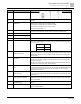
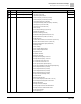
02-13
Multi-function output 1 (RY1)
0: No function
1: Indication during RUN
2: Operation speed reached
3: Desired frequency reached 1 (Pr.02-22)
4: Desired frequency reached 2 (Pr.02-24)
5: Zero speed (Frequency command)
6: Zero speed including STOP (Frequency command)
7: Over-torque 1 (Pr.06-06–06-08)
8: Over-torque 2 (Pr.06-09–06-11)
9: Drive is ready
10: Low voltage warning (Lv) (Pr.06-00)
11: Malfunction indication
13: Overheat warning (Pr.06-15)
14: Software brake signal indicator (Pr.07-00)
15: PID feedback error (Pr.08-13, Pr.08-14)
16: Slip error (oSL)
17: Count value reached, does not return to 0 (Pr.02-20)
18: Count value reached, return to 0 (Pr.02-19)
19: External interrupt B.B. input (Base Block)
20: Warning output
21: Over-voltage
22: Over-current stall prevention
23: Over-voltage stall prevention
24: Operation mode
25: Forward command
26: Reverse command
29: Output when frequency ≥ Pr.02-34
30: Output when frequency < Pr.02-34
31: Y-connection for the motor coil
32: ∆-connection for the motor coil
33: Zero speed (actual output frequency)
34: Zero speed including STOP (actual output frequency)
35: Error output selection 1 (Pr.06-23)
36: Error output selection 2 (Pr.06-24)
37: Error output selection 3 (Pr.06-25)
38: Error output selection 4 (Pr.06-26)
40: Speed reached (including STOP)
42: Crane function
43: Motor speed detection
44: Low current output (use with Pr.06-71–06-73)
45: UVW output electromagnetic valve switch
46: Master dEb output
50: Output control for CANopen
51: Analog output control for RS-485 interface
52: Output control for communication cards
53: Fire mode indication
66: SO output logic A
11
02-16
Multi-function output 2 (MO1)
0
02-17
Multi-function output 3 (MO2)
0