
Operating Instructions

Descriptions of Parameter Settings
Descriptions of Parameter Settings
116 | 443
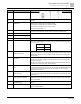
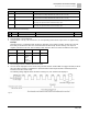
Pr.
Explanation
Settings
Default
67: Analog input level reached
68: SO output logic B
73: Over-torque 3
74: Over-torque 4
75: Forward RUN status
76: Reverse RUN status
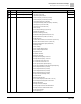
● Use this parameter to set the function of multi-function terminals.
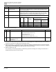
Summary of Function Settings
(Take the normally open contact (N.O.) for example, ON: contact is closed, OFF: contact is open)
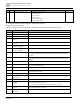
Settings
Functions
Descriptions
0
No Function
Output terminal with no function
1
Indication during RUN
Activates when the drive is not in STOP.
2
Operation speed reached
Activates when output frequency of drive reaches to the setting frequency.
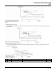
3
Desired frequency reached 1
(Pr.02-22)
Activates when the desired frequency (Pr.02-22) is reached.
4
Desired frequency reached 2
(Pr.02-24)
Activates when the desired frequency (Pr.02-24) is reached.
5
Zero speed
(Frequency command)
Activates when Frequency command = 0. (the drive must be in RUN status)
6
Zero speed including STOP
(Frequency command)
Activates when Frequency command = 0 or stopped.
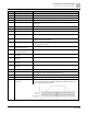
7
Over-torque 1
Activates when the drive detects over-torque. Pr.06-07 sets the over-torque detection
level (motor 1), and Pr.06-08 sets the over-torque detection time (motor 1). See Pr.06-
06–06-08.
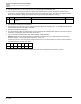
8
Over-torque 2
Activates when the drive detects over-torque. Pr.06-10 sets the over-torque detection
level (motor 2), and Pr.06-11 sets the over-torque detection time (motor 2). See Pr.06-
09–06-11.
9
Drive is ready
Activates when the drive is ON with no error detected.
10
Low voltage warning (Lv)
Activates when the DC bus voltage is too low.
(see Pr.06-00 Low Voltage Level)
11
Malfunction indication
Activates when fault occurs (except Lv stop).
13
Overheat warning
Activates when IGBT or heat sink overheats to prevent the drive from shutting down due
to overheating. (see Pr.06-15)
14
Software brake signal indication
Activates when the soft brake function is ON. (see Pr.07-00).
15
PID feedback error
(Pr.08-13, 08-14)
Activates when the PID feedback signal error is detected.
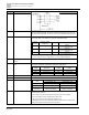
16
Slip error (oSL)
Activates when the slip error is detected.
17
Count value reached, does not
return to 0
(Pr.02-20)
When the drive executes external counter, this contact activates if the count value is
equal to the setting value for Pr.02-20.
This contact deactivates when the setting value for Pr.02-20 > Pr.02-19.
18
Count value reached, returns to 0
(Pr.02-19)
When the drive executes the external counter, this contact activates if the count value is
equal to the setting value for Pr.02-19.
19
External interrupt B.B. input
(Base Block)
Activates when external interrupt (B.B.) stop output occurs in the drive.