
Operating Instructions


Descriptions of Parameter Settings
Descriptions of Parameter Settings
145 | 443
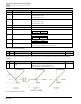
Fig. 59:
Pr.
Explanation
Settings
Default
03-19
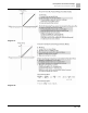
Signal loss selection for analog
input 4 to 20 mA
0: Disable
1: Continue operation at the last frequency
2: Decelerate to 0 Hz
3: Stop immediately and display ACE
0
● Determines the treatment when the 4–20 mA signal is lost (ACIc (Pr.03-29 = 0)).
● When Pr.03-29 ≠ 0, the voltage input to ACI terminal is 0–10 V or 0–20 mA, and Pr.03-19 is invalid.
● When the setting is 1 or 2, the keypad displays the warning code “ANL”. It keeps blinking until the ACI signal is
recovered.
● When the drive stops, the condition that causes the warning does not exist , so the warning automatically
disappears.
Pr.
Explanation
Settings
Default
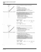
03-20
Multi-function output (AFM)
0 to 23
0
Setting
Function
Description
0
Output frequency (Hz)
Maximum frequency Pr.01-00 is processed as 100 %.
1
Frequency command (Hz)
Maximum frequency Pr.01-00 is processed as 100 %.
2
Motor speed (Hz)
Maximum frequency Pr.01-00 is processed as 100 %.
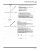
3
Output current (rms)
(2.5 × drive rated current) is processed as 100 %.
4
Output voltage
(2 × motor rated voltage) is processed as 100 %.
5
DC bus voltage
230V series: 450V = 100%
460V series: 900V = 100%
575V series: 1125V = 100%
6
Power factor
-1.000–1.000 = 100%
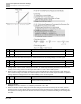
7
Power
(2 × drive rated power) is processed as 100 %.
8
Output torque
Full-load torque = 100 %
9
AVI
0–10 V = 0–100 %
10
ACI
4–20 mA = 0–100 %
12
Iq current command
(2.5 × drive rated current) is processed as 100%.
13
Iq feedback value
(2.5 × drive rated current) is processed as 100%.
14
Id current command
(2.5 × drive rated current) is processed as 100%.