
Operating Instructions


Descriptions of Parameter Settings
Descriptions of Parameter Settings
147 | 443
Pr.
Explanation
Settings
Default
03-27
AFM output bias
-100.00 to 100.00%
0.00
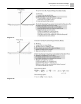
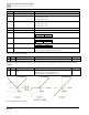
● Example 1: AFM 0–10 V is set to the output frequency, the output equation is
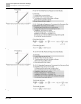
● Example 2: AFM 0–20 mA is set to the output frequency, the output equation is
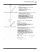
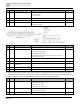
● Example 3: AFM 4–20 mA is set to the output frequency, the output equation is
●
● This parameter sets the corresponding voltage of the analog output 0.
Pr.
Explanation
Settings
Default
03-28
AVI terminal input selection
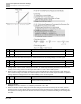
0: 0 to 10V (Pr.03-63–Pr.03-68 is valid)
3: -10 to 10V (Pr.03-69–Pr.03-74 are valid)
0
03-29
ACI terminal input selection
0: 4 to 20 mA
1: 0 to 10V
2: 0 to 20 mA
0
● When you change the input mode, verify that the external terminal switch (ACI) position is correct.
● When you change the setting, proportion to the corresponding AVI and ACI will change to default.
Pr.
Explanation
Settings
Default
03-30
PLC analog output terminal status
Monitor the status of the PLC analog output terminals
bit 0: AFM
Read only
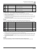
Fig. 61:
Example:
When Pr.03-30 displays 0001 (hex) (that is, the value is 1 (decimal) and 1 (binary)), it means that AFM is used by
PLC.