
Operating Instructions


Descriptions of Parameter Settings
Descriptions of Parameter Settings
173 | 443
● When using the AVI terminal, you must set Pr.03-28 to 1 and switch AVI voltage to 0–10 V. At this time, the AVI
input impedance is 20 KΩ.
● When the temperature reaches to the set protection level, the motor acts according to the settings for Pr.06-29
and displays warning “oH3” (if Pr.06-29 = 1–3). When the temperature is lower than the set protection level,
you can press RESET key to clear the fault.
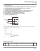
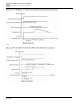
● The PTC uses the AVI-input and is connected through divider resistance as shown below:
1. The voltage between +10V to ACM: lies within 10–11V.
2. The impedance for AVI is around 20K Ω. Recommended value for divider resistance is 1K–10K Ω.
3. Please contact your motor dealer for the curve of temperature and resistance value for PTC.
Protection level (Pr.06-30) = V+10 * (RPTC//20K) / [R1+(RPTC//20K)]
● V+10: voltage between +10V-ACM actual value, Range 10.4~11.2VDC;
● RPTC: motor PTC overheat protection level;
● 20K Ω: the AVI input impedance;
● R1: divider resistance (recommended value: 1–10k Ω)
Fig. 75:
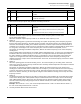
Take the standard PTC thermistor as an example: if the protection level is 1330 Ω, the actual voltage between
+10V-ACM is 10.5 V and divider resistance R1 is 4.4k Ω.
Fig. 76:
See the following calculation when Pr.06-30 is set to 23% and motor temperature overheating protection level is
1330 Ω:
1330//20000 = (1330*20000) / (1330+20000) = 1247.07
10.5 * 1247.07 / (4400+1247.07) = 2.32 (V) ≒ 2.3 (V)
Pr.06-30 = 2.3 / 10 V * % = 23%
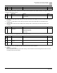
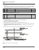
Pr.
Explanation
Settings
Default
06-31
Frequency command at
malfunction
0.00 to 599.00 Hz
Read only