
Operating Instructions

Descriptions of Parameter Settings
Descriptions of Parameter Settings
183 | 443
Pr.
Explanation
Settings
Default
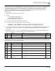
06-71
Low current setting level
0.0 to 100.0%
0.0
06-72
Low current detection time
0.00 to 360.00 sec.
0.00
06-73
Low current action
0: No function
1: Fault and coast to stop
2: Fault and ramp to stop by the second deceleration time
3: Warn and continue operation
0
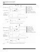
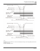
The drive operates according to the setting for Pr.06-73 when the output current is lower than the setting for Pr.06-
71 and when the time of the low current exceeds the detection time for Pr.06-72. Use this parameter with the
external multi-function output terminal setting 44 (low current output).
The low current detection function does not execute when drive is in sleep or standby status.
Pr.
Explanation
Settings
Default
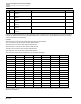
06-80
Fire mode
0: Disable
1: Forward (counterclockwise) operation
2: Reverse (clockwise) operation
0
Use this parameter with multi-function input terminal setting 58 or 59, and multi-function output terminal setting 53
or 54.
0: Fire detection is invalid.
1: The motor operates in a counterclockwise direction (U, V, W).
2: The motor operates in a clockwise direction (U, W, V).
Pr.
Explanation
Settings
Default
06-81
Operating frequency in fire mode
0.00 to 599.00 Hz
60.00
06-88
Operation times in fire mode
0 to 65535 times
Read only
Description Group 07
07 Special Parameters
indicates the parameter can be set during operation.
Pr.
Explanation
Settings
Default
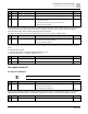
07-00
Software brake chopper action
level
115V/230V models: 350.0 to 450.0 Vdc
460V models: 700.0 to 900.0 Vdc
575V models: 875.0 to 1000.0 Vdc
370.0
740.0
950.0
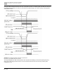
Sets the DC bus voltage at which the brake chopper is activated. Choose a suitable brake resistor to achieve the
optimal deceleration performance. See Chapter 7 Optional Accessories for information about brake resistors.
Pr.
Explanation
Settings
Default
07-01
DC brake current level
0 to 100%
0