
Operating Instructions


Descriptions of Parameter Settings
Descriptions of Parameter Settings
196 | 443
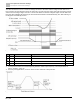
This parameter is set to 1.00 automatically when Pr.00-11 (Speed Control Mode) is changed from V/F mode to
vector mode. Otherwise, it is automatically set to 0.00. Apply the slip compensation after load and acceleration.
Increase the compensation value from small to large gradually; add the output frequency to the [motor rated slip x
Pr.07-27 (Slip Compensation Gain)] when the motor is at the rated load. If the actual speed ratio is slower than
expected, increase the parameter setting value; otherwise, decrease the setting value.
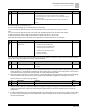
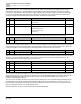
Pr.
Explanation
Settings
Default
07-29
Slip deviation level
0.0 to 100.0%
0: No detection
0
07-30
Over-slip deviation detection time
0.0 to 10.0 sec.
1.0
07-31
Over-slip deviation treatment
0: Warn and continue operation
1: Fault and ramp to stop
2: Fault and coast to stop
3: No warning
0
Pr.07-29–Pr.07-31 set the allowable slip level/time and the over-slip treatment when the drive is running.
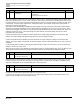
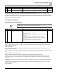
Pr.
Explanation
Settings
Default
07-32
Motor oscillation compensation
factor
0 to 10000
1000
If there are current wave motions which cause severe motor oscillation in some specific area, setting this parameter
can effectively improve this situation. (When running with high frequency or PG, set this parameter to 0. When the
current wave motion occurs in low frequency and high power, increase the value for Pr.07-32.)
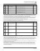
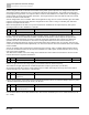
Pr.
Explanation
Settings
Default
07-33
Auto-restart interval of fault
0.0 to 6000.0 sec.
60.0
When a reset/restart occurs after a fault, the drive uses Pr.07-33 as a timer and starts counting the number of faults
within this time period. Within this period, if the number of faults does not exceed the setting for Pr.07-11, the
counting clears and starts from 0 when the next fault occurs.
Pr.
Explanation
Settings
Default
07-46
OOB sampling time
0.1 to 120.0 sec.
1.0
07-47
Number of OOB sampling times
00 to 32
20
07-48
OOB average sampling angle
Read only
Read only
07-38
PMSVC voltage feed forward gain
0.50 to 2.00
1.00
You can use the OOB (Out Of Balance Detection) function with the PLC program in the washing machine system.
When the multi-function input terminal Pr.02-01–02-07 is set to 82 (OOB loading balance detection), the Pr.07-48
(OOB Average Sampling Angle) Δθ value is set according to Pr.07-46 (OOB Sampling Time) and Pr.07-47
(Number of OOB Sampling Times).
The PLC or host controller determines the motor speed according to the Pr.07-48 (OOB Average Sampling Angle)
Δθ value. When the Average Sampling Angle Δθ value is large, the load is unbalanced. In this case, the PLC or
host controller must decrease the Frequency command. Otherwise, increase the Frequency command to execute
high speed operations when Pr.07-48 Δθ value is small.
Related parameters: Pr.02-01–Pr.02-07 (Multi-function Input Commands).