
Operating Instructions


Descriptions of Parameter Settings
Descriptions of Parameter Settings
200 | 443
Use the integral controller to eliminate the deviation during stable system operation. The integral control does not
stop working until the deviation is zero. The integral is affected by the integral time. The smaller the integral time,
the stronger the integral action. It is helpful to reduce overshoot and oscillation for a stable system. Accordingly, the
speed to lower the steady-state deviation decreases. The integral control is often used with the other two controls
for the PI controller or PID controller.
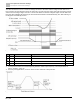
Sets the integral time of the I controller. When the integral time is long, there is a small I controller gain, with slower
response and slow external control. When the integral time is short, there is a large I controller gain, with faster
response and rapid external control.
When the integral time is too short, it may cause overshoot or oscillation for the output frequency and system.
Set Integral Time to 0.00 to disable the I controller.
Pr.
Explanation
Settings
Default
08-03
Differential time (D)
0.00 to 1.00 sec.
0.00
Use the differential controller to show the system deviation change, as well as to preview the change in the
deviation. You can use the differential controller to eliminate the deviation in order to improve the system state.
Using a suitable differential time can reduce overshoot and shorten adjustment time; however, the differential
operation increases noise interference. Note that a too large differential causes more noise interference. In
addition, the differential shows the change and the differential output is 0 when there is no change. Note that you
cannot use the differential control independently. You must use it with the other two controllers for the PD controller
or PID controller.
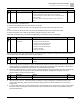
Sets the D controller gain to determine the deviation change response. Using a suitable differential time reduces
the P and I controllers overshoot to decrease the oscillation for a stable system. A differential time that is too long
may cause system oscillation.
The differential controller acts on the change in the deviation and cannot reduce the interference. Do not use this
function when there is significant interference.
Pr.
Explanation
Settings
Default
08-04
Upper limit of integral control
0.0 to 100.0%
100.0
Defines an upper bound for the integral gain (I) and therefore limits the master frequency.
The formula is: Integral upper bound = Maximum Operation Frequency (Pr.01-00) × (Pr.08-04%).
An excessive integral value causes a slow response due to sudden load changes and may cause motor stall or
machine damage. If so, decrease it to a proper value.
Pr.
Explanation
Settings
Default
08-05
PID output command limit
(positive limit)
0.0 to 110.0%
100.0
Defines the percentage of the output frequency limit during the PID control. The formula is Output Frequency Limit
= Maximum Operation Frequency (Pr.01-00) × Pr.08-05%.
Pr.
Explanation
Settings
Default
08-06
PID feedback value by
communication protocol
-200.00 to 200.00%
0.00
Use communications to set the PID feedback value when the PID feedback input is set to communications (Pr.08-
00 = 7 or 8).