
Operating Instructions

Descriptions of Parameter Settings
Descriptions of Parameter Settings
214 | 443
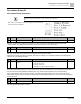
Pr.
Explanation
Settings
Default
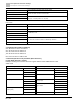
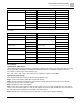
09-04
COM1 communication protocol
1: 7, N, 2 (ASCII)
2: 7, E, 1 (ASCII)
3: 7, O, 1 (ASCII)
4: 7, E, 2 (ASCII)
5: 7, O, 2 (ASCII)
6: 8, N, 1 (ASCII)
7: 8, N, 2 (ASCII)
8: 8, E, 1 (ASCII)
9: 8, O, 1 (ASCII)
10: 8, E, 2 (ASCII)
11: 8, O, 2 (ASCII)
12: 8, N, 1 (RTU)
13: 8, N, 2 (RTU)
14: 8, E, 1 (RTU)
15: 8, O, 1 (RTU)
16: 8, E, 2 (RTU)
17: 8, O, 2 (RTU)
1
Control by PC (Computer Link)
When using the RS-485 serial communication interface, you must specify each drive’s communication address in
Pr.09-00. The computer then implements control using the drives’ individual addresses.
Modbus ASCII (American Standard Code for Information Interchange): Each byte of data is the combination of two
ASCII characters. For example, one byte of data: 64 Hex, shown as ‘64’ in ASCII, consists of ‘6’ (36Hex) and ‘4’
(34Hex).
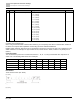
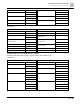
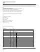
Code Description
The communication protocol is in hexadecimal, ASCII: 0 … 9, A … F, every hexadecimal value represents an
ASCII code. The following table shows some examples.
Character
‘0’
‘1’
‘2’
‘3’
‘4’
‘5’
‘6’
‘7’
ASCII code
30H
31H
32H
33H
34H
35H
36H
37H
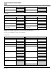
Character
‘8’
‘9’
‘A’
‘B’
‘C’
‘D’
‘E’
‘F’
ASCII code
38H
39H
41H
42H
43H
44H
45H
46H
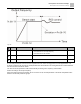
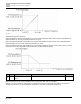
Data Format
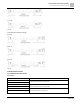
10-bit character frame (For ASCII):
(7, N, 2)
Fig. 103:
(7, E, 1)