
Operating Instructions

Descriptions of Parameter Settings
Descriptions of Parameter Settings
216 | 443
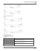
DATA 0
n ≤ 16, maximum of 32 ASCII codes (20 sets of data)
LRC Check High
LRC checksum:
one 8-bit checksum consists of 2 ASCII codes
LRC Check Low
END High
End characters:
END High = CR (0DH), END Low = LF (0AH)
END Low
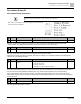
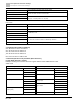
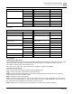
RTU mode:
START
Defined by a silent interval of larger than/equal to 10 ms
Address
Communication address: 8-bit binary address
Function
Command code: 8-bit binary command
DATA (n-1)
Contents of data:
n × 8-bit data, n ≤ 16
…….
DATA 0
CRC Check Low
CRC checksum:
one 16-bit CRC checksum consists of 2 8-bit binary characters
CRC Check High
END
Defined by a silent interval of larger than/equal to 10 ms
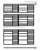
3.2 Communication Address (Address)
00H: Broadcast to all AC motor drives
01H: AC motor drive at address 01
0FH: AC motor drive at address 15
10H: AC motor drive at address 16
:
FEH: AC motor drive at address 254
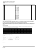
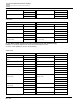
3.3 Function (Function code) and DATA (Data characters)
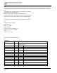
(1) 03H: Read data from a register
Example: Reading two continuous data from register address 2102H. AMD address is 01H.
ASCII mode:
Command Message
Response Message
STX
‘:’
STX
‘:’
Address
‘0’
Address
‘0’
‘1’
‘1’
Function
‘0’
Function
‘0’
‘3’
‘3’
Starting register
‘2’
Number of register
(count by byte)
‘0’
‘1’
‘4’
‘0’
Content of starting
register 2102H
‘1’
‘2’
‘7’
Number of register
(count by word)
‘0’
‘7’
‘0’
‘0’
‘0’
Content of register 2103H
‘0’