
Operating Instructions

Descriptions of Parameter Settings
Descriptions of Parameter Settings
219 | 443
‘8’
The second data content
‘0’
‘F’
‘A’
‘0’
LRC Check
‘9’
‘A’
END
CR
LF
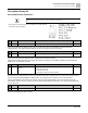
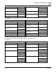
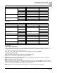
RTU mode:
Command Message
Response Message
ADR
01H
ADR
01H
CMD
10H
CMD 1
10H
Target register
05H
Target register
05H
00H
00H
Number of register
(count by word)
00H
Number of register
(count by word)
00H
02H
02H
Quantity of data (byte)
04
CRC Check Low
41H
The first data content
13H
CRC Check High
04H
88H
The second data content
0FH
A0H
CRC Check Low
‘9’
CRC Check High
‘A’
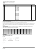
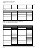
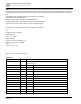
3.4 Checksum
(1) ASCII mode (LRC Check):
LRC (Longitudinal Redundancy Check) is calculated by summing up the values of the bytes from ADR1 to the last
data character then calculating the hexadecimal representation of the 2’s-complement negation of the sum.
For example, as shown in the above Section 3.3.(1),
01H + 03H + 21H + 02H + 00H + 02H = 29H, the 2’s-complement negation of 29H is D7H.
(2) RTU mode (CRC Check):
CRC (Cyclical Redundancy Check) is calculated by the following steps:
Step 1: Load a 16-bit register (called CRC register) with FFFFH.
Step 2: Exclusive OR the first 8-bit byte of the command message with the low order byte of the 16-bit CRC
register, and put the result in the CRC register.
Step 3: Examine the LSB of CRC register.
Step 4: If the LSB of CRC register is 0, shift the CRC register one bit to the right, fill MSB with zero, then repeat
step 3. If the LSB of CRC register is 1, shift the CRC register one bit to the right, fill MSB with zero, Exclusive OR
the CRC register with the polynomial value A001H, then repeat step 3.
Step 5: Repeat step 3 and 4 until you perform eight shifts. This processes a complete 8-bit byte.