
Operating Instructions
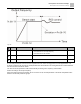

Descriptions of Parameter Settings
Descriptions of Parameter Settings
220 | 443
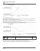
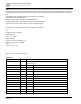
Step 6: Repeat step 2 through 5 for the next 8-bit byte of the command message. Continue doing this until all bytes
are processed. The final contents of the CRC register are the CRC value. When transmitting the CRC value in the
message, the upper and lower bytes of the CRC value must be swapped, that is, the lower order byte is transmitted
first.
The following is an example of CRC generation using C language.
The function takes two arguments:
Unsigned char* data ← a pointer to the message buffer
Unsigned char length ← the quantity of bytes in the message buffer
The function returns the CRC value as a type of unsigned integer.
Unsigned int crc_chk(unsigned char* data, unsigned char length)
{
int j;
unsigned int reg_crc=0Xffff;
while(length--){
reg_crc ^= *data++;
for(j=0;j<8;j++){
if(reg_crc & 0x01){ /* LSB(b0)=1 */
reg_crc=(reg_crc>>1) ^ 0Xa001;
}else{
reg_crc=reg_crc >>1;
}
}
}
return reg_crc; // return register CRC
}
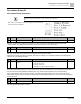
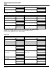
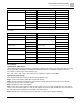
Address list
Content
Address
Function
AC motor drive parameters
GGnnH
GG is the parameter group, nn is the parameter number; for example, the address of
Pr.04-10 is 040AH.
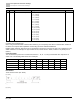
Command write only
2000H
bit 1–0
00B: No function
01B: Stop
10B: Run
11B: JOG + RUN
bit 3–2
Reserved
bit 5–4
00B: No function
01B: FWD
10B: REV
11B: Change direction
bit 7–6
00B: 1
st
accel. / decel.
01B: 2
nd
accel. / decel.
10B: 3
rd
accel. / decel.
11B: 4
th
accel. / decel.