
Operating Instructions


Descriptions of Parameter Settings
Descriptions of Parameter Settings
224 | 443
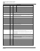
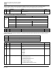
10b: Error
bit 4 0b: Motor drive does not output
1b: Motor drive outputs
bit 5 0b: No warning
1b: Warning
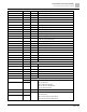
2227H
Drive’s estimated output torque (positive or negative direction) (XXXX Nt-m)
2228H
Reserved
2229H
KWH display (XXXX.X)
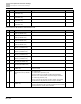
222AH
Reserved
222BH
Reserved
222CH
Reserved
222DH
Reserved
222EH
PID target value (XXX.XX %)
222FH
PID offset (XXX.XX %)
2230H
PID output frequency (XXX.XX Hz)
2231H
Reserved
2232H
Display the auxiliary frequency
2233H
Display the master frequency
2234H
Display the frequency after adding and subtracting of the master and auxiliary
frequencies.
Exception response:
When the drive is using the communication connection, if an error occurs, the drive responds to the error code and
sets the highest bit (bit 7) of the command code to 1 (function code AND 80H) then responds to the control system
to signal that an error occurred.
If the keypad displays CE-XX as a warning message, XX is the error code at that time. See the table of error codes
for communication error for reference.
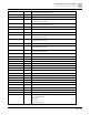
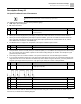
Example:
ASCII mode:
RTU mode:
STX
‘:’
Address
01H
Address
‘0’
Function
86H
‘1’
Exception code
02H
Function
‘8’
CRC Check Low
C3H
‘6’
CRC Check High
A1H
Exception code
‘0’
‘2’
LRC Check
‘7’
‘7’
END
CR
LF
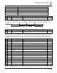
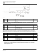
The following table describes the exception code.