
Operating Instructions


Descriptions of Parameter Settings
Descriptions of Parameter Settings
229 | 443
Description Group 10
10 Speed Feedback Control Parameters
indicates the parameter can be set during operation.
The following abbreviations are used in this parameter group:
● ASR: Adjust Speed Regulator
● PG: Pulse Generator
Pr.
Explanation
Settings
Default
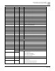
10-00
Encoder type selection
0: Disabled
5: Pulse input (MI7)
0
● When you use MI7 single-phase pulse input, you must use it with Pr.00-20=4, Pr.10-00=0 and Pr.10-16=5.
● When you use MI7 single-phase pulse input as speed feedback, you must use it with Pr.10-00=5 and Pr.10-
02=5. The drive calculates the MI7 single-phase pulse input speed when the control modes are VF, VFPG,
SVC IM/PM FOC sensorless, and IM/PM TQC
● The MS300 does not support the full position control pulse command input function.
Pr.
Explanation
Settings
Default
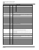
10-01
Encoder pulses per revolution
1 to 20000
600
● This parameter sets the encoder pulses per revolution (PPR). It is a feedback control signal source when using
PG. The encoder sets the number of pulses for the motor rotating through one rotation. The A/B phase cycle
generates the pulse number.
● This setting is also the encoder resolution. The speed control is more accurate with higher resolution.
● If you set this parameter incorrectly, it may cause motor stall, drive over-current, or a permanent magnetic pole
origin detection error for the PM motor in closed-loop control. When using the PM motor, you must perform the
magnetic pole origin detection (Pr.05-00 = 13) again if you modify the content of this parameter.
Pr.
Explanation
Settings
Default
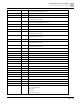
10-02
Encoder input type setting
0: Disable
5: Single-phase input (MI7)
0
Pr.
Explanation
Settings
Default
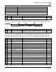
10-04
Electrical gear at load side A1
1 to 65535
100
10-05
Electrical gear at motor side B1
1 to 65535
100
10-06
Electrical gear at load side A2
1 to 65535
100
10-07
Electrical gear at motor side B2
1 to 65535
100
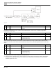
Use Pr.10-04–Pr.10-07 with the multi-function input terminal setting 48 to switch to Pr.10-04– Pr.10-05 or Pr.10-
06–Pr.10-07, as shown in the following diagram.