
Operating Instructions

Descriptions of Parameter Settings
Adjustment and Application
261 | 443
Pr.
Explanation
Settings
Default
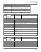
10-31
I/F mode, current command
0 to 150% rated current of the motor
40
Sets the current command for the drive in the low speed area (low speed area: Frequency command < Pr.10-39).
When the motor stalls on heavy duty start-up or forward/reverse with load, increase the parameter value. If the
inrush current is too high and causes oc stall, then decrease the parameter value.
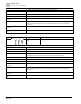
Pr.
Explanation
Settings
Default
10-32
PM FOC sensorless speed
estimator bandwidth
0.00 to 600.00 Hz
5.00
● Sets the speed estimator bandwidth. Adjust the parameter to influence the stability and the accuracy of the
motor speed.
● If there is low frequency vibration (the waveform is similar to a sine wave) during the process, then increase the
bandwidth. If there is high frequency vibration (the waveform shows extreme vibration and is like a spur), then
decrease the bandwidth.
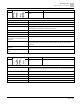
Pr.
Explanation
Settings
Default
10-34
PM sensorless speed estimator
low-pass filter gain
0.00 to 655.35
1.00
● Influences the response speed of the speed estimator.
● If there is low frequency vibration (the waveform is similar to a sine wave) during the process, then increase the
gain. If there is high frequency vibration (the waveform shows extreme vibration and is like a spur), then
decrease the gain.
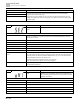
Pr.
Explanation
Settings
Default
10-39
Frequency point to switch from I/F
mode to PM sensorless mode
0.00 to 599.00 Hz
20.00
● Sets the frequency for the switch point from low frequency to high frequency.
● Due to the weak back-EMF in the low frequency area, PM sensorless mode cannot estimate the accurate
speed and position of the rotor. Thus, using I/F mode control is more suitable. In the medium-to-high frequency
area, PM sensorless can accurately estimate the back-EMF, stabilizes and controls the motor with lower
current.
● If the switch point is too low and PM sensorless mode operates at a too low frequency, the motor does not
generate enough back-EMF to let the speed estimator measure the right position and speed of the rotor, and
causes stall and oc when running at the switch point frequency.
● If the switch point is too high, the drive easily runs in the frequency area of the I/F mode for a long time, which
generates a larger current and cannot save energy. (If the current for Pr.10-31 is too high, the high switch point
makes the drive continue to output with the setting value for Pr.10-31.)
Pr.
Explanation
Settings
Default
10-42
Initial angle detection pulse value
0.0 to 3.0
1.0
● The angle detection is fixed to 3: Use the pulse injection method to start. The parameter influences the value of
the pulse during the angle detection. The larger the pulse, the higher the accuracy of rotor’s position. A larger
pulse might cause oc.
● Increase the parameter when the running direction and the command are opposite during start-up. If oc occurs
at start-up, then decrease the parameter.
● See Section Adjustment & Application for detailed motor adjustment procedure.