
Operating Instructions


Summary of Parameter Settings
00 Drive Parameters
33 | 443
Pr.
Explanation
Settings
Default
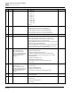
7: Reset CANopen Slave index
8: Keypad does not respond
9: Reset all parameters to defaults (base frequency is 50 Hz)
10: Reset all parameters to defaults (base frequency is 60 Hz)
11: Reset all parameters to defaults with base frequency at 50 Hz (keep
the user-defined parameter values Pr.13-01–Pr.13-50)
12: Reset all parameters to defaults with base frequency at 60 Hz (keep
the user-defined parameter values Pr.13-01–Pr.13-50)
00-03
Start-up display
0: F (frequency command)
1: H (output frequency)
2: U (user-defined, see Pr.00-04)
3: A (output current)
0
00-04
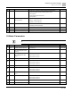
Content of multi-function display
(user-defined)
0: Display output current (A) (unit: Amp)
1: Display counter value (c) (unit: CNT)
2: Display the drive’s actual output frequency (H.) (unit: Hz)
3: Display the drive’s DC bus voltage (V) (unit: V
DC
)
4: Display the drive’s output voltage (E) (unit: V
AC
)
5: Display the drive’s output power angle (n) (unit: deg)
6: Display the drive’s output power (P) (unit: kW)
7: Display the motor speed rpm (r) (unit: rpm)
8: Display the drive’s estimated output torque, motor’s rated torque is
100% (t) (unit: %)
10: Display PID feedback (b) (unit: %)
11: Display AVI analog input terminal signal (1.) (unit: %)
12: Display ACI analog input terminal signal (2.) (unit: %)
14: Display the drive’s IGBT temperature (i.) (unit:
o
C)
16: The digital input status (ON / OFF) (i)
17: The digital output status (ON / OFF) (o)
18: Display multi-step speed (S)
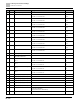
19: The corresponding CPU digital input pin status (d)
20: The corresponding CPU digital output pin status (0.)
22: Pulse input frequency (S.)
25: Overload count (0.00–100.00%) (o.) (unit: %)
26: Ground fault GFF (G.) (unit: %)
27: DC bus voltage ripple (r.) (unit: V
DC
)
28: Display PLC register D1043 data (C)
30: Display the output of User-defined (U)
31: Display Pr.00-05 user gain (K)
35: Control mode display:
● 0 = Speed control mode (SPD)
● 1 = Torque control mode (TQR) (t.)
36: Present operating carrier frequency of the drive (J.) (Unit: Hz)
38: Display the drive status (6.)
39: Display the drive’s estimated output torque, positive and negative,
using Nt-m as unit (t 0.0: positive torque; -0.0: negative torque) (C.)
40: Torque command (L.) (unit: %)
41: kWh display (J) (unit: kWh)
42: PID target value (h.) (unit: %)
3