
Operating Instructions


CANopen Overview
CANopen Communication Interface Descriptions
358 | 443
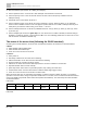
1. Wire the hardware (See Section 15-2 Wiring for CANopen).
2. Set the operation source: set Pr.00-21 to 3 for CANopen communication card control.
3. Set the frequency source: set Pr.00-20 to 6. Choose the source for the Frequency command from the
CANopen setting.
4. Set DS402 as the control mode: Pr.09-40=1
5. Set the CANopen station: set Pr.09-36; the range is between 1 and 127. When Pr.09-36 = 0, the CANopen
slave function is disabled. Note that if an error appears (station address error CAdE or CANopen memory error
CFrE) when you finish the station setting, set Pr.00-02 = 7 to reset.
6. Set the CANopen baud rate: set Pr.09-37 (CANBUS baud rate: 1 M (0), 500 K (1), 250 K (2), 125 K (3), 100 K
(4) or 50 K (5)).
7. Set the multiple input functions to Quick Stop. You can also choose to enable or disable; the default setting is
disabled. To enable the function, set MI terminal to 53 in one of the following parameters: Pr.02-01–02-07. Note
that this function is available in DS402 only.
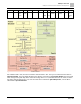
The status of the motor drive (following the DS402 standard)
According to the DS402 definition, the motor drive is divided into 3 blocks and 9 statuses as described below:
3 blocks
● Power Disable: without PWM output
● Power Enable: with PWM output
● Fault: one or more errors have occurred.
9 statuses
● Start: power on
● Not Ready to Switch On: the motor drive is initiating.
● Switch On Disable: occurs when the motor drive finishes initiating.
● Ready to Switch On: warming up before running.
● Switch On: the motor drive has the PWM output, but the reference command is not effective.
● Operation Enable: able to control normally.
● Quick Stop Active: when there is a Quick Stop request, stop running the motor drive.
● Fault Reaction Active: the motor drive detects conditions which might trigger error(s).
● Fault: one or more errors have occurred in the motor drive.
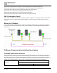
When the motor drive turns on and finishes the initiation, it remains in Ready to Switch On status. To control the
operation of the motor drive, change to Operation Enable status. To do this, set the control word's bit0–bit3 and bit7
of the Index 6040H and pair with Index Status Word (Status Word 0X6041). The control steps and index definition
are described below.
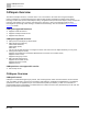
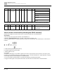
Index 6040
15–9
8
7
6–4
3
2
1
0
Reserved
Halt
Fault Reset
Operation
Enable
operation
Quick Stop
Enable Voltage
Switch On
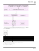
Index 6041