
Operating Instructions

CANopen Overview
CANopen Communication Interface Descriptions
363 | 443
Set the Standard (New definition) as the control mode: Pr.09-40 = 0 and 09-30 = 1.
Set the CANopen station: set Pr.09-36; the range is between 1–127. When Pr.09-36=0, the CANopen slave
function is disabled. Note that if an error appears (station address error CAdE or CANopen memory error CFrE)
when you finish the station setting, set Pr.00-02 = 7 to reset.
Set the CANopen baud rate: set Pr.09-37 (CANBUS baud rate: 1 M (0), 500 K (1), 250 K (2), 125 K (3), 100 K (4)
and 50 K (5))
Various mode control method (New Standard)
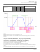
Speed Mode:
1. Set MS300 to speed control mode: set index 6060 = 2.
2. Set the target frequency: set 2060-03, unit is Hz, with 2 decimal places. For example, 1000 is 10.00 Hz.
3. Operation control: set 2060-01 = 008H for server on, and set 2060-01 = 0081H for running.
Fig. 126:
Control DI/DO/AI/AO through CANopen
To control the DO and AO of the motor drive through CANopen, follow these steps:
1. Define the DO to be controlled by CANopen. For example, set Pr.02-13 = 50 to control RY1.
2. Define the AO to be controlled by CANopen. For example, set Pr.03-20 = 20 to control AFM.
3. Control the Index mapped by CANopen. To control DO, use control Index 2026-41. To control AO, use control
2026-A1. To set RY1 as ON, set bit 0 of Index 2026-41 = 1, then RY1 outputs 1. To control AFM output =
50.00%, set Index 2026-A1 = 5000, then AFM outputs 50%.