
Operating Instructions

CANopen Overview
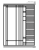
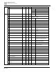
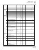
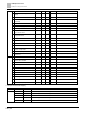
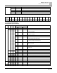
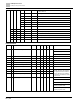
CANopen Supported Index
367 | 443
D
Display motor speed (rpm)
0
R
U16
E
Reserved
F
Reserved
10
Power output (X.XXX kWH)
0
R
U16
17
Multi-function display (Pr.00-04)
0
R
U16
2022H
0
Reserved
0
R
U16
1
Display the drive’s output current
0
R
U16
2
Counter value
0
R
U16
3
Actual output frequency (XXX.XX Hz)
0
R
U16
4
DC bus voltage (XXX.X V)
0
R
U16
5
Output voltage (XXX.X V)
0
R
U16
6
Power factor angle (XX.X°)
0
R
U16
7
Display the output power of U, V, W in
kW
0
R
U16
8
Display the motor speed estimated by
the drive or encoder feedback in rpm
0
R
U16
9
Display the positive / negative output
torque estimated by the drive (+0.0:
positive torque; -0.0: negative torque)
0
R
U16
A
Reserved
B
Display the PID feedback value after
enabling the PID function in % (to two
decimal places)
0
R
U16
C
Display the AVI analog input terminal
signal, 0–10 V corresponds to 0.00–
100.00% (see Explanation 1 in Pr.00-
04)
0
R
U16
D
Display the ACI analog input terminal
signal, 4–20 mA / 0–10 V corresponds
to 0.00–100.00% (2.) (see
Explanation 2 in Pr.00-04)
0
R
U16
F
IGBT temperature of the power
module in
o
C
0
R
U16
2022H
11
The digital input status (ON / OFF),
refer to Pr.02-12
(see Explanation 2 in Pr.00-04)
0
R
U16
12
The digital output status (ON / OFF),
refer to Pr.02-18
(see Explanation 3 in Pr.00-04)
0
R
U16
13
Current step for the multi-step speed
operation
0
R
U16
14
The corresponding CPU digital input
pin status (d.)
(see Explanation 3 in Pr.00-04)
0
R
U16
15
The corresponding CPU digital output
pin status (O.)
(see Explanation 4 in Pr.00-04 )
0
R
U16