
Operating Instructions


Safe Torque Off Function
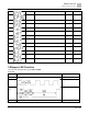
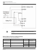
Wiring Diagram
378 | 443
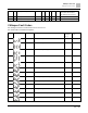
Terminals
Terminal Function
Descriptions
+24 V
When the STO function is not used,
you can disable the STO function by
shorting S1 and S2 with + 24 V.
Output voltage range: +24V ± 10%
Output voltage capacity: 100 mA
S1
Signal input for STO function channel
1
S1–DCM / S2–DCM
Rated input voltage: +24 Vdc ± 10%;
maximum input voltage: +30 Vdc ± 10%
Rated input current: 6.67 mA ± 10%
STO activation mode
Input voltage level: 0 Vdc < S1–DCM and S2–DCM < 5 Vdc
STO response time: ≤ 20 ms (time required for S1 / S2 to operate until the
drive stops outputting)
STO cut-off mode
Input voltage level: 11 Vdc < S1–DCM and S2–DCM < 30 Vdc
S2
Signal input for STO function channel
2
DCM
Reference ground for S1 and S2
signal
Table 17-1: STO terminal function description
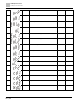
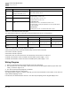
The table below describes the action logic and keypad display after the S1 / S2 signal input.
Signal
Status
S1–DCM
ON
ON
OFF
OFF
S2–DCM
ON
OFF
ON
OFF
Drive output
Ready to output
STL2 mode
(Torque output off)
STL1 mode
(Torque output off)
STO mode
(Torque output off)
Error displayed on the
keypad
No error displayed
STL2
STL1
STO
Table 17-2: Action logic and keypad display description
STO means channel 1 and 2 operate simultaneously and enter Safe Torque Off.
STL1 means channel 1 operates.
STL2 means channel 2 operates.
STL3 means there is an error detected in the internal loop of the channel 1 or channel 2.
S1–DCM / S2–DCM ON: means S1–DCM / S2–DCM inputs a power supply > 11 V
DC
.
S1–DCM / S2–DCM OFF: means S1–DCM / S2–DCM inputs a power supply < 5 V
DC
.
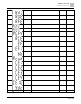
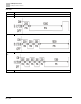
Wiring Diagram
1. Figure 17-2 shows the internal circuit diagram of the safe control loop.
2. The terminals of the safe control loop + 24V-S1-S2 are short-circuited together with the jumper wire at the
factory, as shown in Figure 17-2.
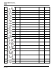
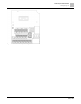
3. The safe control loop wiring diagram is as follows:
Remove the jumper wire from +24V-S1-S2.
The wiring is shown in Figure 17-3 below. Normally, you must close the ESTOP contact switch, so the drive can
output without displaying an error.
In STO mode, the switch ESTOP is turned on. The drive stops outputting and the keypad displays STO.