
Operating Instructions

Optional Accessories
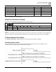
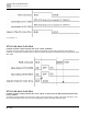
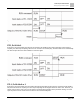
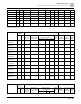
Brake Resistors and Brake Units Used in AC Motor Drives
390 | 443
RT001X-53N
1
0.75
0.5
80W 750Ω
BR080W750
1
-
1.2
280.0
4
4.5
RT002X-53N
2
1.5
1
200W 360Ω
BR200W360
1
-
2.6
186.7
6
6.7
RT003X-53N
3
2.2
1.5
300W 400Ω
BR300W400
1
-
2.3
160.0
7
7.8
RT005X-53N
5
3.7
2.5
500W 100Ω
BR500W100
1
-
9.2
93.3
12
13.4
RT0075-53N
7.5
5.5
3.7
750W 140Ω
BR750W140
1
-
6.6
80.0
14
15.7
RT010X-53N
10
7.5
5.1
1000W 75Ω
BR1K0W075
1
-
12.3
70.0
16
17.9
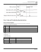
Table 18: 575V three-phase.
*1
Calculation for 125% brake torque: (kW)*125%*0.8; where 0.8 is motor efficiency. Due to the limited resistor
power, the longest operation time for 10% ED is 10 seconds (ON: 10 sec./OFF: 90 sec.).
*2
The brake resistor calculation is based on a four-pole motor (1800 rpm).
*3
For heat dissipation, a resistors of 400 W or lower should be fixed to the frame and maintain the surface
temperature below 4822°F (250°C); a resistor of 1000 W and above should maintain the surface
temperature below 662°F (350°C). (If the surface temperature is higher than the temperature limit, install
extra cooling or increase the size of the resistor.)
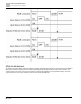
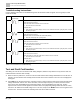
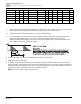
1. Select the resistance value, power and brake usage (ED%) per requirements.
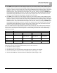
2. Definition for Brake Usage ED%
3. For safety, install a thermal overload relay (OL) between the brake unit and the brake resistor in conjunction
with the magnetic contactor (MC) before the drive for additional protection. The thermal overload relay protects
the brake resistor from damage due to frequent or continuous braking. Under such circumstances, turn off the
power to prevent damage to the brake resistor, brake unit and drive.
NOTE: Never use it to disconnect the brake resistor.