
Operating Instructions


Optional Accessories
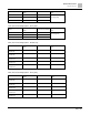
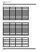
Brake Resistors and Brake Units Used in AC Motor Drives
391 | 443
4. Any damage to the drive or other equipment caused by using brake resistors and brake modules that are not
provided by Siemens voids the warranty.
5. Consider environmental safety factors when installing the brake resistors. If you use the minimum resistance
value, consult local dealers for the power calculation.
6. When using more than two brake units, the equivalent resistor value of the parallel brake unit cannot be less
than the value in the column “Min. Resistor Value (Ω)”. Read the wiring information in the brake unit instruction
sheet thoroughly prior to operation. Visit the following links to get the instruction sheets for the wiring in the
brake unit:
7. The selection tables are for normal usage. If the AC motor drive requires frequent braking, increase the Watts
by two to three times.
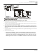
8. Thermal Overload Relay (TOR):
Thermal overload relay selection is based on its overload capacity. A standard braking capacity of the
Climatix VFD is 10% ED (Tripping time=10 s). As shown in the figure below, a 460V, 1kw Climatix VFD
required the thermal relay to take 260% overload capacity for 10 seconds (hot starting) and the braking
current is 24A. In this case, select a thermal overload relay rated at 10 A (10 * 260% = 26A > 24A). The
property of each thermal relay may vary among different manufacturers. Carefully read the specification
before using it.