
Operating Instructions

Optional Accessories
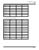
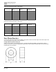
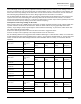
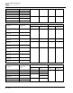
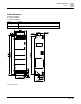
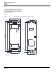
Zero Phase Reactors
403 | 443
Unit: Inches (mm)
Model
A
B
C
T60006L2040W453
22.5
43.1
18.5
T60006L2050W565
36.3
53.5
23.4
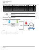
Installation
During installation, pass the cable through at least one zero phase reactor. Use a suitable cable type (pressure
endurance, current endurance, insulation class, and wire gauge) so that the cable passes easily through the zero
phase reactor. Do not pass the grounding cable through the zero phase reactor; only pass the motor wire and
power cable through the zero phase reactor. With longer motor cables the zero-phase reactor can effectively
reduce interference at the motor output. Pay extra attention to the large leakage current due to long cable length.
This may cause temperature rise in the zero phase reactor. Install the zero phase reactor as close to the output of
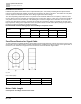
the drive as possible. The figure below shows the installation diagram for a single turn zero phase reactor. If the
wire diameter allows several turns, see below for the installation of a multi-turn zero phase reactor. The more turns,
the better the noise suppression effect.
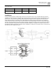
Fig. 135: Single turn wiring diagram for shielding wire with a zero phase reactor
Multi-turn zero phase reactor