
Operating Instructions

Optional Accessories
Zero Phase Reactors
404 | 443
Installation Precaution
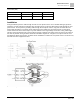
Install the zero phase reactor at the drive’s output terminal (U/T1, V/T2, W/T3). Installing the zero phase reactor
reduces the electromagnetic radiation and load stress emitted by the wiring of the drive. The number of zero phase
reactors required for the drive depends on the wiring length and the drive voltage.
The normal operating temperature of the zero phase reactor should be lower than 176°F (85°C). However, when
the zero phase reactor is saturated, its temperature may exceed 176°F (85°C). In this case, increase the number of
zero phase reactors to avoid saturation. The following are reasons that might cause saturation of the zero phase
reactors: the drive wiring is too long; the drive has several sets of loads; the wiring is in parallel; or the drive uses
high capacitance wiring. If the temperature of the zero phase reactor exceeds 176°F (85°C) during the operation of
the drive, increase the number of zero phase reactors.
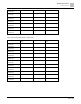
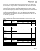
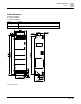
Recommended maximum wiring gauge when installing a zero phase reactor
Zero Phase Reactor
Model No.
Max. Wire Gauge or
LUG width
Max. Wire Gauge AWG (1Cx3)
Max. Wire Gauge AWG (4Cx1)
75°C
90°C
75°C
90°C
T600006L2040W453
11 mm
9 AWG
4 AWG
6 AWG
6 AWG
T600006L2050W565
16 mm
1 AWG
2/0 AWG
1 AWG
1/0 AWG
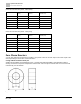
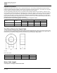
Zero Phase Reactor for Signal Cable
To solve interference problems between signal cables and electrical equipment, install a zero phase reactor on the
signal cable. See the table below for models and dimensions. Installing a zero phase reactor on the signal cable at
the source of the interference suppresses the interference and noise between signal cables.
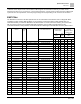
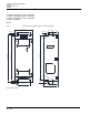
Fig. 136:
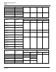
Unit: Inches (mm)
Model
A
B
C
T60004L2016W620
10.7
17.8
8.0
T60004L2025W622
17.5
27.3
12.3
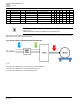
Motor Cable Length
Consequence of leakage current on the motor