
Operating Instructions


Summary of Parameter Settings
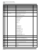
02 Digital Input / Output Parameters
42 | 443
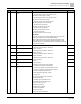
Pr.
Explanation
Settings
Default
24: FWD JOG command
25: REV JOG command
26: TQC / FOC mode selection
27: ASR1 / ASR2 selection
28: Emergency stop (EF1)
29: Signal confirmation for Y-connection
30: Signal confirmation for ∆-connection
31: High torque bias (Pr.11-30)
32: Middle torque bias (Pr.11-31)
33: Low torque bias (Pr.11-32)
38: Disable writing EEPROM function
39: Torque command direction
40: Force coasting to stop
41: HAND switch
42: AUTO switch
48: Mechanical gear ratio switch
49: Enable drive
50: Slave dEb action to execute
51: Selection for PLC mode bit 0
52: Selection for PLC mode bit 1
53: Trigger CANopen quick stop
56: Local / Remote selection
58: Enable fire mode (with RUN command)
59: Enable fire mode (without RUN command)
70: Force auxiliary frequency return to 0
71: Disable PID function, force PID output return to 0
72: Disable PID function, retain the output value before disabled
73: Force PID integral gain return to 0, disable integral
74: Reverse PID feedback
81: Simple positioning zero point position signal input
82: OOB loading balance detection
83: Multi-motor (IM) selection bit 0
84: Multi-motor (IM) selection bit 1
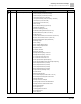
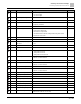
02-09
UP / DOWN key mode
0: UP / DOWN by the acceleration / deceleration time
1: UP / DOWN constant speed (Pr.02-10)
2: Pulse signal (Pr.02-10)
3: External terminals UP / DOWN mode
4: External terminals UP / DOWN mode (Pr.02-10)
0
02-10
Constant speed, acceleration /
deceleration speed of the
UP/DOWN Key
0.001–1.000 Hz/ms
0.001
02-11
Multi-function input response time
0.000–30.000 sec.
0.005
02-12
Multi-function input mode
selection
0000h–FFFFh (0: N.O.; 1: N.C.)
0000
02-13
Multi-function output 1 (RY1)
0: No function
1: Indication during RUN
11
02-16
Multi-function output 2 (MO1)
0