
Operating Instructions


Option Cards
Option Card Installation
432 | 443
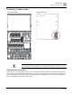
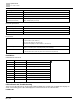
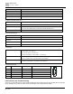
Communication Card
RT-DNET-COMM, RT-CAN-COMM,
RT-PROFIB-COMM
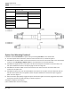
Frame
Mounting Position 1
Mounting Position 2
Cable Model No.
Cable Model No.
A
RT-COMMCBL-A
RT-COMMCBL-C
B
RT-COMMCBL-D
C
RT-COMMCBL-B
D
E
N/A
F
RT-COMMCBL- A
RT-COMMCBL-C
RT-COMMCBL-B
RT-COMMCBL-D
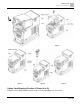
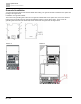
Option Card Mounting Position 1
Installation method: Back-mount the option card by connecting flat cables to the control board.
3. Turn off the power of the motor drive, and then remove the front cover, as shown in Figure A.
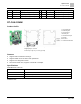
3. Assemble the connection cable: Connect the connector at one end of the connection cable to the control board
connector. See The Wiring of Option Cards for more information on connection methods.
3. Assemble the supported frame of the option card: Aim the two clips at the two slots on the motor drive, and
then press downward to have the two clips engage the slots. See Figure B.
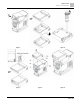
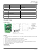
4. Assemble the connection cable: Connect the connector at the other end of the connection cable to the
connector of the option card.
5. Assemble the option card: Have the terminal block and connector of the option card face downward, aim the
two holes of the option card to the position column and press downward so that the three clips engage the
option card. See Figure C.
6. Ensure that three clips properly engage the option card and then tighten the screws (suggested torque value:
4–6 kg-cm [3.5–5.2 lb-in.] [0.39–0.59 Nm]), as shown in Figure D.
Assembly is completed. See Figure E.
(Take communication card as an example)