
Operating Instructions


Summary of Parameter Settings
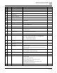
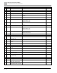
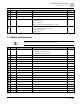
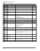
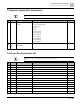
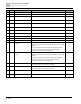
10 Speed Feedback Control Parameters
66 | 443
Pr.
Explanation
Settings
Default
10-04
Electrical gear at load side A1
1 to 65535
100
10-05
Electrical gear at motor side B1
1 to 65535
100
10-06
Electrical gear at load side A2
1 to 65535
100
10-07
Electrical gear at motor side B2
1 to 65535
100
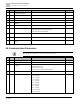
10-10
Encoder stall level
0: No function
0 to 120%
115
10-11
Detection time of encoder stall
0.0 to 2.0 sec.
0.1
10-12
Encoder stall action
0: Warn and continue operation
1: Fault and ramp to stop
2: Fault and coast to stop
2
10-13
Encoder slip range
0: Disable
0 to 50%
50
10-14
Detection time of encoder slip
0.0 to 10.0 sec.
0.5
10-15
Encoder stall and slip error action
0: Warn and continue operation
1: Fault and ramp to stop
2: Fault and coast to stop
2
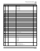
10-16
Pulse input type setting
0: Disabled
5: Single-phase input (MI7)
0
10-17
Electrical gear A
1 to 65535
100
10-18
Electrical gear B
1 to 65535
100
10-21
PG2 pulse input speed command
low pass filter time
0.000 to 65.535 sec.
0.100
10-24
FOC & TQC function control
0 to 65535
0
10-25
FOC bandwidth for speed
observer
20.0 to 100.0 Hz
40.0
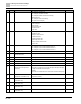
10-26
FOC minimum stator frequency
0.0 to 10.0% fN
2.0
10-27
FOC low pass filter time constant
1 to 1000 ms
50
10-28
FOC gain for excitation current
rise time
33 to 100% Tr
100
10-29
Upper limit of frequency deviation
0.00 to 200.00 Hz
20.00
10-31
I/F mode, current command
0 to 150% rated current of the motor
40
10-32
PM FOC sensorless speed
estimator bandwidth
0.00 to 600.00 Hz
5.00
10-34
PM sensorless speed estimator
low-pass filter gain
0.00 to 655.35
1.00
10-35
AMR (Kp) gain
0.00 to 3.00
1.00
10-36
AMR (Ki) gain
0.00 to 3.00
0.20
10-39
Frequency point to switch from I/F
mode to PM sensorless mode
0.00 to 599.00 Hz
20.00
10-40
Frequency point to switch from
PM sensorless mode to I/F mode
0.00 to 599.00 Hz
20.00