
Data Sheet for Product
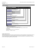
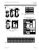
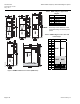
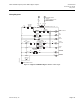
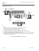
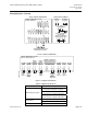
Table Of Contents

Submittal Sheet SED2 Variable Frequency Drives With C-Bypass Options
Document No. 154-044
May 9, 2011
Wiring Diagrams continued
1111098765432
VFD1 CONTROL TERMINALS
RR M2
M2
(6) (10)
M1
(5) (6)
(T1)
OL1
1T1
1T2
(T2)
(T3)
1T3
M
(1) (2)
M2
(1) (2)
U
V
(3)
(5) (6)
(4)
W
(3) (4)
U
VFD1
W
GND
V
R
S
T
AC MOTOR
(CUSTOMER
SUPPLIED)
GND
LUG
GND
GND
LUG
2L1
2L2
2L3
3L1
3L2
3L3
FU1
1L1
1L2
(L1)
L1
L2
(T1)
DISC1
M3
(2)
(4)
(6)
1L3
(L3)
L3
(T3)
GND
(L2)(T2)
1L1 1L2
(5)
(3)
(1)
POWER FUSES - MAIN SHORT
CIRCUIT PROTECTION BY OTHERS
(SEE NOTE 1)
DRIVE INPUT
CONTACTOR
POWER
SUPPLY
3 PHASE
60 Hz
TO
STEP-DOWN
CONTROL
TRANSFORMER
B2
A2A1
B1
C2C1
OPTIONAL
INPUT LINE
REACTOR
(SUPPLIED
LOOSE)
A2
B2
C2
A1
B1
C1
OPTIONAL
OUTPUT LOAD
REACTOR
(SUPPLIED
LOOSE)
A2
B2
C2
A1
B1
C1
OPTIONAL
INPUT LINE
REACTOR
VFD0240R1
NOTES:
1. Branch circuit protection to be provided by installer, per UL508A, if not provided with drive.
2. For bypass operation, modify these drive parameters: P0704[0] and P0704[1] = 3.
3. Control and communication wiring should be 300V UL minimum.
4. Communication wiring should be run with maximum separation possible from all other wiring.
5. Essential service mode operates the motor full speed (bypass) with no protection for the motor or system.
6. Ensure that automatic bypass will not damage the system before activating.
7. See Publication No. 125-3215 SED2 Conventional Bypass Options Operating Instructions, for proper fuse and wire sizes.
8. See Publication No. 125-3201 SED2 Variable Frequency Drives Start-Up, Operation and Maintence Manual, for SED2
VFD input/output control signal wiring details.
Figure 4. C-Bypass and NEMA 12 Bypass Power Circuit.
Page 6 of 9 Siemens Industry, Inc.