
Operating Instructions

SED2 VFD Startup, Operation, and Maintenance Manual
18 Siemens Building Technologies, Inc.
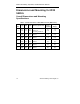
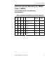
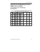
Mounting Dimensions
9.3
(235)
Frame Size A
Frame Size B
Frame Size C
Frame Size D
Frame Size E
6.3
(160)
0.17
(4.5)
0.22
(5.5)
5.4
(138)
0.19
(4.8)
6.9
(174)
6.9
(174)
0.22
(5.5)
8.0
(204)
0.68
(17.5)
19.1
(486)
9.3
(235)
0.68
(17.5)
24.3
(616)
Frame Size F
15
(381)
0.59
(15)
51
(1295)
VFD0092R2
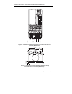
Figure 6. Mounting Dimensions of NEMA Type 1 SED2
in Inches (Millimeters).
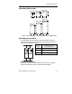
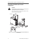
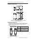
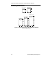
Mounting Instructions
The NEMA Type 1 SED2 must have a minimum clearance at the top
and bottom for ventilation and equipment access. In addition, allow
12-inches (305 mm) of space between each SED2 to allow for
sufficient heat dissipation.
Frame
Size
V
min Minimum Clearance
in Inches (Millimeters)
A, B, C 4 (100)
D, E 11-3/4 (300)
F 13-3/4 (350)
SED2
VFD0143R1
V
min.
V
min.
V
min.
V
min.
12 Inches
(305 mm)
SIEMENS SIEMENS
SED2