
Operating Instructions

Electrical Installation
Siemens Building Technologies, Inc. 43
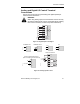
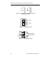
Analog Input DIP Switches
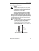
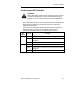
WARNING:
When using analog inputs, the DIP switches must be correctly
set and the analog inputs correctly configured before being
enabled. If this is not done, the motor may start inadvertently.
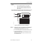
After completing settings for motor frequency and unit of measurement
DIP switches, and wiring for input power and motor connections,
reattach the I/O module.
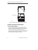
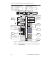
For all versions of the SED2, the DIP switches used to configure the
analog inputs are located on the I/O module. (See Access to
Connection Terminals section for disassembly instructions.)
DIP
Switch
Position Function
OFF
Analog Input 1, voltage 0 to 10 Vdc, factory default.
OFF Analog Input 1, Ni 1000 sensor input with parameter setting
P0756[0]=5.
1
ON Analog Input 1, current 0 to 20 mA.
OFF Analog Input 2, voltage 0 to 10 Vdc, factory default.
OFF Analog Input 2, Ni 1000 sensor input with parameter setting
P0756[1]=5.
2
ON Analog Input 2, current 0 to 20 mA.