
Operating Instructions

Electrical Installation
Siemens Building Technologies, Inc. 45
NOTE:
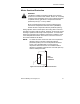
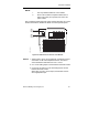
1. Use only shielded cables for control cables.
2. Route control cables in separate cable trunks at
least 7-3/4 inches (20 cm) away from motor and
power cables.
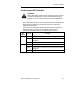
After completing analog input DIP switch settings and wiring for control
terminal connections, reattach the SED2 cover and operator panel.
20 21
22
23 24 25
29 3017 26 27 2812 13 14 15 16
10 11678912345
ON
1
RL1
NC
RL1
NO
RL1
COM
RL2
NC
RL2
NO
RL2
COM
AOUT
1+
AOUT
1-
PTC
A
PTC
B
DIN
5
DIN
6
AOUT
2+
AOUT
2-
ISO
0V
P+ N-
10V 0V AIN
1+
AIN
1-
DIN
1
DIN
2
DIN
3
DIN
4
ISO
24V
AIN
2+
AIN
2-
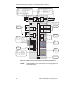
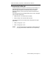
AIN1
On = [A], 0 - 20 mA
Off = [V], 0 - 10 V
AIN2
On = [A], 0 - 20 mA
Off = [V], 0 - 10 V
2
VFD0017R1
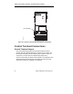
Figure 29. SED2 Control Terminals on I/O Module.
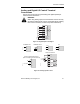
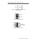
NOTES: 1. Analog inputs 1 and 2 can be optionally configured for direct
connection of a Ni 1000 temperature sensor. The sensor
connects between terminals 4 and 2 or 11 and 2.
2. 0 to 10 Vdc analog inputs connect between terminals 2 and 3.
3. 0 mA to 20 mA and 4 mA to 20 mA analog inputs connect
between terminals 3 and 4.
When using a 4 mA to 20 mA input, DIP switches must be
set to appropriate input.