
Operating Instructions

Electrical Installation
Siemens Building Technologies, Inc. 47
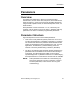
Analog and Digital I/O Control Terminal
Connections
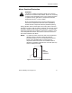
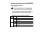
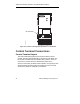
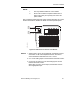
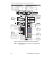
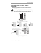
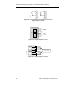
Figures 31 through 35 show typical analog and digital input/output
control terminal connections.
WARNING:
When using analog inputs, the DIP switches must be correctly
set and the analog inputs correctly configured before enabling
them. If this is not done, the motor may start inadvertently.
VFD0048R1
5
6
7
9
16
17
28
PNP
NPN
DIN1
DIN2
DIN3
DIN4
DIN5
DIN6
8
or
ISOLATED +24 Vdc
(OUTPUT)
ISOLATED 0 Vdc
(OUTPUT)
DC-ISOLATED
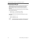
Figure 31. Digital Inputs 1 through 6.
2
3
4
EXTERNAL 0-20 mA
3
2
-
+
EXTERNAL 0-10V
VFD0022R1
4
2
Ni-1000
VFD0175R1
15
14
PTC
VFD0176R1
2
3
4
VFD 24V dc Powered 0-20 mA Device
28
9
mA
24V ac Power
(Power consumption cannot exceed 100 mA)
VFD0021R1
VFD0050R1
1
2
3
10
11
AIN1+
4
MINIMUM
4.7k OHM
AIN1-
AIN2+
AIN2-
+10 V
0 V
A/D
A/D
SPEED POTENTIOMETER
Figure 32. Analog Inputs 1 and 2.