
Data Sheet for Product

Technical Bulletin
Document No. 155-743
TB255
August 29, 2018
Motor Performance on
PWM/IGBT AC Drives
Siemens Industry, Inc.
Abstract
Use of PWM (Pulse Width Modulation) drives in HVAC systems has proven both efficient
and cost effective. However, their effect on motor insulation must be understood to
ensure consistent, long, and trouble free operation. This bulletin will explain PWM
fundamentals, their effects on motors, and appropriate field actions to ensure consistent,
trouble-free motor operation.
Conventional PWM
Drive Fundamentals
(Figure 1)
Conventional PWM drives consist of:
• Six-pulse diode rectifier to convert AC line voltage to a constant fixed level DC
voltage.
• DC link capacitor that acts as a filter to smooth the DC link voltage and help keep it
constant. The DC link voltage level is approximately 1.4 times the AC line voltage.
• Isolated Gate Bipolar Transistor (IGBT) inverter to convert the DC link voltage to a
variable voltage, variable frequency 3-phase output for controlling the speed and
torque of an induction motor and for providing overload capabilities necessary for
high dynamic motor performance.
• Micro-processor based controller to supervise the operation of the inverter as well as
to implement power control algorithms to obtain optimum dynamic performance from
the induction motor.
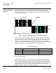
Figure 1. PWM Drive Single Line Diagram.
Rectifier
D C Link
Inverter
Three Phase
60 Hz. Power
+
-
Motor