
Data Sheet for Product

Technical Bulletin – TB255 Motor Performance on PWM/IGBT AC Drives
Document Number 155-743
August 29, 2018
Page 2 Siemens Industry, Inc.
Effects of PWM
Drives on Motors
(Figure 2)
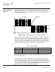
PWM is the method by which the IGBTs are modulated to produce the fundamental
voltage and frequency to the motor. The IGBTs are pulsed on and off rapidly (100 to 200
nanoseconds) to produce a carrier frequency. The carrier frequency travels over the
motor cables, which are acting as transmission lines, to “carry” the appropriate voltage
and frequency to the motor.
VOLTAGE CURRENT
0V
TIME
Figure 2. Switching frequencies of 2, 4, 8…16 kHz are Common.
Figure 2. Switching frequencies of 2, 4, 8…16 kHz are Common.
When the IGBT is switched, a voltage edge (leading edge) is created that also travels
along the motor cables. Because of an impedance mismatch between the inverter end
and the motor end of the cable, some portion of the waveform is reflected back toward
the drive. If this reflection coincides with another leading edge, the two will be added
together. In some cases this “reflective wave” phenomenon can cause high voltage levels
at the motor terminals, as high as 2.5 times the DC bus voltage of the drive.
Table 1. Motor Voltages.
Supply Voltage
Typical Peak Motor Voltage Levels
Maximum Peak Voltage *
230
575
810
460
1150
1610
600
1500
2100
* Actual cable length, cable type, motor inductance and switching frequency can all have
an effect on peak voltages.
Motor insulation stress can be caused by both the high voltage change with respect to
time (dV/dT), and the high peak voltage caused by the reflective wave. This insulation
stress can result in a phase-to-phase or phase-to-stator short in the first windings of the
motor, due to the motor’s high inductance and winding capacitance causing the voltage to
dissipate rapidly. These types of voltage-induced insulation failures may occur very
quickly, sometimes in as little as a few weeks of operation.