
Data Sheet for Product

Motor Performance on PWM/IGBT AC Drives Technical Bulletin TB255
Document Number 155-743
August 29, 2018
Siemens Industry, Inc. Page 3
Minimizing Motor
Failures
To offset the high dV/dT and the high-peak voltage effects on motors there are several
precautions that can be taken:
• Use inverter-rated motors
It is best practice to always use inverter duty motors when the application is controlled
by a drive. NEMA Standard MG-1 indicates that inverter duty motors be designed to
withstand 1600V peak and a rise time >0.1 microsecond.
Inverter duty motors generally are also “perfectly wound”, that is they are wound to
ensure the greatest possible separation between the first and last windings.
Additionally, a higher temperature rated insulation is used.
On new construction, inverter duty motors are an extremely good value considering
the life cycle benefit they provide. Standard motors will have a shorter life than
Inverter Duty motors, regardless of connection cable distance, because drive
fundamentals dictate that they see the higher DC bus voltage instead of the AC line
voltage. The use of Inverter duty motors generally allows the motor to be at the
distance specified by the VFD manufacturer that guarantees the drives’ optimum
performance.
• Minimize motor cable length
The longer the motor cables, the higher the wire capacitance and lower the wire
impedance, thus a higher chance of mismatch between drive and motor impedance,
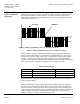
and an increased chance of high motor terminal voltages. This is most critical on
systems operating at higher voltages (460V to 480V or 575V to 600V), because of
their corresponding constant high DC bus levels and peak voltage levels (See page
1). Peak voltages can be reached in as little as 25 feet of cable.
• Reduce switching frequency
Often installations do not require extremely quiet motor operation, as their location is
a mechanical room. Higher IGBT switching frequencies reduce the motor’s audible
sound, but increase the number of times per second the motor is subjected to the
peak voltages. Operate at reduced IGBT switching frequencies whenever possible.
• Use load reactors
Load reactors increase the voltage rise time and the decreased peak voltages at the
motor terminals by adding inductance in the line. Generally, the use of output reactors
allow motors to be as far as 300 wire feet from the VFD without being adversely
affected by the VFD output. At distances above those listed by the VFD
manufacturer, the manufacturer should be contacted to ensure that the VFD will not
have to be de-rated to deliver the appropriate power to the motor.
• Use dV/dT filter (Also called drive-applied filters and LC filters.)
These filters combine both capacitance and inductance and can generally protect
motors from the effects of a PWM drive output for up to 1000 feet. At distances
above those listed by the VFD manufacturer, the manufacturer should be contacted
to ensure that the VFD will not have to be de-rated to deliver the appropriate power to
the motor.
• Use motor manufacturer specification guide
Electrical insulation systems vary dramatically by motor type and the manufacturers
are in the best position to gauge their particular motor’s performance when used with
IGBT drives. Most motor manufacturers issue guidelines that must be followed when
used with AC drives to support their warranty. Use this to help guide your decision or
contact the motor manufacturer for assistance.