
Operating Instructions


SED2 AOP Operating Instructions
12 Siemens Building Technologies
AOP Applications
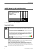
Single Drive Control Using the AOP
Per default, the AOP is configured to work with only one SED2 in Local mode. In Local mode, the
AOP normally mounts directly onto the SED2. The RS-232 and RS-485 ports handle
communications. Full operator control of the SED2 is available with access to all normal drive and
AOP internal parameters.
To configure a single SED2 VFD with the AOP as the control source, follow the procedure in the
Quick Commissioning section of this manual.
Network Setup (RS-485 with Panel Mounting Kit)
The AOP has the capability to control up to 31 SED2 VFDs connected as a network. In a network
configuration, a unique two-digit number identifies each VFD. When the AOP connects to a
network of SED2 VFDs, there are two Master Modes of operation:
The AOP can access a single SED2 VFD on the network with full control/parameter access.
The AOP can use the Broadcast mode to simultaneously start/stop all drives on the network.
Use the following procedure to set up a network of SED2 VFDs under control of an AOP:
1. Use the standard panel mounting kit (PMK) to connect RS-485 communications as follows:
Correct wiring for PMK and SED2 VFD is as follows:
Pin 3 = +24V
Pin 4 = 0V
Pin 29 and 30 = RS-485 communications
Use twisted pair cable or shielded cable (preferred).
The end-of-line SED2 VFD must have a 120-ohm terminating resistor across RS-485
Pins 1 and 2.
Use a common ground for all SED2 VFDs and the PMK.
For the first issue of the PMK, for correct communications DIP Switch 1=UP or ON on
the PMK board.
2. Configure the SED2 VFDs for network use.
Set the Command Source P0700[1]=5 (USS on Com Link). This sets the control over the
USS link on the communications port.
Assign each drive a unique RS-485 USS address in the range of 0 to 30. To do this set
User Access Level P0003=3 (expert) and use USS Address for Serial Interface Com Link
P2011[0] to assign a unique address to each SED2 VFD.