
Operating Instructions


SED2 Conventional Bypass Option Operating Instructions
4 Siemens Building Technologies, Inc.
Conventional Bypass Option
Overview
General Description
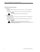
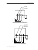
During normal operation in a typical
application, the input and output
contactors close and the SED2
operates the motor (Figure 1). The
bypass contactor provides the ability to
operate the motor on utility power and
eliminate the VFD from the motor
control circuit.
Drive
Motor
2 Contactor Bypass
Input
Device
Drive
Motor
3 Contactor Bypass
Input
Device
VFD0008R1
Figure 1. Functional Diagram of Typical Bypass Option.
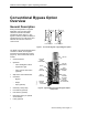
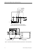
The SED2 Conventional Bypass Option
consists of a SED2, and a bypass
enclosure with Conventional controls
(Figure 2). The Conventional controls
include:
• Control terminals
• Operators
− "Drive-Off-Bypass" switch
− "Bypass On" light
− "Drive Test On-Off" switch
(optional)
• Step-down control transformer
• Contactors:
− Bypass
− Output
− Input (optional)
• Overload (current) relay
• Line Reactor (optional)
• Load reactor (optional)
• Disconnect switch (or optional
circuit breaker)
• Fuses (optional)
REACTOR
(OPTIONAL)
INPUT
CONTACTOR
(OPTIONAL)
STEP-DOWN
POWER
TRANSFORMER
OUTPUT
CONTACTOR
BYPASS
CONTACTOR
DISCONNECT
SWITCH
(OR OPTIONAL
CIRCUIT BREAKER)
SED2 VFD
RELAYS
FUSES
(OPTIONAL)
OVERLOAD
(CURRENT)
RELAY
VFD0156R1
Figure 2. Typical SED2 Conventional Bypass Option
Components.