
Operating Instructions


SED2 Conventional Bypass Option Operating Instructions
14 Siemens Building Technologies, Inc.
INPUT POWER
WIRING VIA
KNOCKOUT
MOTOR
WIRING VIA
KNOCKOUT
BYPASS
CONTACTOR
OUTPUT
CONTACTOR
DISCONNECT
SWITCH OR
CIRCUIT BREAKER
MOTOR
OVERLOAD
CTB1
L1 L2 L3
T1 T2 T3
VFD0123R1
GROUND LUGS (2)
SED 2
VFD
INPUT POWER
WIRING VIA
KNOCKOUT
MOTOR
WIRING VIA
KNOCKOUT
BYPASS
CONTACTOR
OUTPUT
CONTACTOR
DISCONNECT SWITCH
(OR OPTIONAL
CIRCUIT BREAKER)
MOTOR
OVERLOAD
GROUND
LUGS (2)
L3 L2 L1
T3 T2 T1
CTBI
SED2
VFD
INPUT
CONTACTOR
(OPTIONAL)
TRANSFORMER
POWER FUSES
(OPTIONAL)
REACTOR
(OPTIONAL)
COMMUNICATIONS
WIRING (P1) VIA
1 KNOCKOUT
VFD0159R1
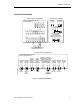
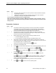
Figure 10. Routing of Power and Control
Wiring for Frame Sizes A
Through E (NEMA 1).
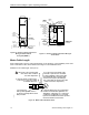
Figure 11. Routing of Power and Control Wiring for
Frame Size F.
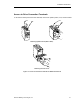
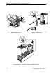
Motor Cable Length
Motor cable length is given to ensure performance of only the drive, not the suitability of the motor
when connected to a drive at this distance. See Figure 12 for installation notes.
Maximum motor cable length: 164 ft (50 m)
M
SED2
3. If needed, use
SBT-specified input line reactors
to ensure a good impedance match
with your drive.
1. Never run control or drive input
wires in the same conduit as
the drive output wires.
4. If a disconnect is mounted on the
load side of your drive, it is desirable
to wire an auxiliary contact to the drive
that will disable drive operation when
the disconnect opens. (The wiring for
this contact must not be run in the same
conduit as the drive output wires).
5. Inverter duty motors are recommended.
Install motors within their guidelines. Use
dV/dT filters, output reactors, or other load
conditioners as applicable or as specified
by the motor manufacturer. Reactor products
must be mounted next to the drive.
2. Keep the distance from the drive
to the motor as short as possible
to maximize motor life.
VFD0014R3
!
Figure 12. Motor Cable Installation Notes.